OLED 128×32
A narrow 0.91-inch monochrome OLED strip, 128 by 32 pixels, driven by an SSD1306 over two I2C wires.
- ControllerSolomon Systech SSD1306, 128 × 64 driver with a built-in display RAM
- Logic supply (VDD)1.65 V to 3.3 V
- Panel supply7 V to 15 V; the internal charge pump generates 7.5 V from the low supply
- Absolute maximumVDD -0.3 V to +4 V; inputs VSS - 0.3 V to VDD + 0.3 V
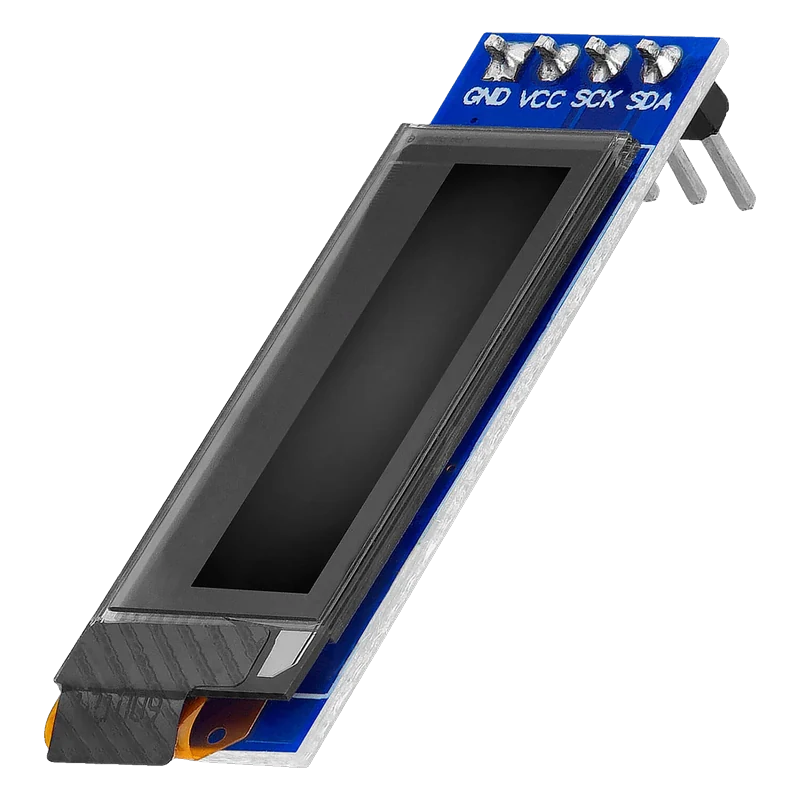
The 0.91-inch OLED is a 128 × 32 pixel monochrome panel on a four-pin I2C board (GND, VCC, SCK, SDA) driven by Solomon Systech's SSD1306, whose logic runs at 1.65 V to 3.3 V while an on-chip charge pump makes the 7.5 V the panel needs (SSD1306 datasheet Rev 1.1, pp. 6, 62). It answers at I2C address 0x3C (the SSD1306 offers 0x3C or 0x3D, p. 19) and is driven with Adafruit_SSD1306 set to 128 × 32. Power it from 3.3 V and it is safe on an Uno, an ESP32 and a Pico alike.
This is the slim OLED strip, about 38 mm long, that shows two to four lines of text or a small graph without a backlight. Each of its 128 × 32 pixels emits its own light, so contrast is high and it reads well from wide angles. The SSD1306 controller holds a 128 × 64 bit frame buffer and 256 contrast steps (SSD1306 datasheet Rev 1.1, p. 6); this panel uses half of the rows.
Only four wires are needed. The board breaks out GND, VCC, SCK and SDA (SCK is the I2C clock, SCL), with the SSD1306's address pin tied so it answers at 0x3C. Inside, the SSD1306's charge pump turns the low supply into the 7.5 V that drives the OLED (p. 62), so there is no separate panel supply to provide. Most of these boards add a small regulator and I2C pull-up resistors, which is why they also accept 5 V on VCC.
Libraries draw into a frame buffer in the microcontroller's RAM and send it with display(). On an Uno, a 128 × 32 buffer costs 512 bytes of its 2 KB, half of what a 128 × 64 screen takes, which leaves room for other libraries. Adafruit_SSD1306 with Adafruit GFX gives text, lines and bitmaps; U8g2 is the alternative when RAM is tight.
OLED 128×32 pinout
| Pin | Function | Type |
|---|---|---|
| GND | Ground | power in |
| VCC | Supply3.3 V (most boards also accept 5 V) | power in |
| SCK | I2C SCL3.3 V logic | input |
| SDA | I2C SDA3.3 V logic | bidirectional |
How to wire the OLED 128×32
Pin by pin, for the board you have.
| OLED 128×32 | Arduino Uno | Note |
|---|---|---|
| GND | GND | |
| VCC | 3.3V | |
| SCK | A5 (SCL) | |
| SDA | A4 (SDA) |
- Powered from 3.3V the module's pull-ups hold the bus near 3.3 V, which the Uno reads as HIGH and the SSD1306 tolerates.
| OLED 128×32 | ESP32 DevKit V1 | Note |
|---|---|---|
| GND | GND | |
| VCC | 3V3 | |
| SCK | GPIO22 (D22) | |
| SDA | GPIO21 (D21) |
- Do not power the module from VIN (5 V): on many boards the pull-ups then lift SDA and SCL to 5 V, above what ESP32 pins accept.
| OLED 128×32 | Raspberry Pi Pico | Note |
|---|---|---|
| GND | GND | |
| VCC | 3V3(OUT) | |
| SCK | GP5 | |
| SDA | GP4 |
- Do not power the module from VBUS or VSYS: the pull-ups would then lift SDA and SCL above the Pico's 3.3 V pins.
OLED 128×32 code
Every example here compiles for its board.
// OLED 128×32 on Arduino Uno: wiring and a free simulation at https://www.tinkered.ai/components/oled-128x32
// 0.91" SSD1306 128x32 OLED on an Arduino Uno: SDA A4, SCL A5, address 0x3C
#include <Wire.h>
#include <Adafruit_GFX.h>
#include <Adafruit_SSD1306.h>

const int SCREEN_WIDTH = 128;
const int SCREEN_HEIGHT = 32;
Adafruit_SSD1306 display(SCREEN_WIDTH, SCREEN_HEIGHT, &Wire, -1); // no reset pin

void setup() {
  Serial.begin(115200);
  if (!display.begin(SSD1306_SWITCHCAPVCC, 0x3C)) {
    Serial.println(F("SSD1306 not found at 0x3C: check wiring"));
    while (true) {}
  }
  display.clearDisplay();
  display.setTextColor(SSD1306_WHITE);
  display.setTextSize(1);
  display.setCursor(0, 0);
  display.println(F("0.91in OLED ready"));
  display.display();
  Serial.println(F("OLED ready"));
  delay(1000);
}

void loop() {
  unsigned long seconds = millis() / 1000;
  display.clearDisplay();
  display.setTextSize(1);
  display.setCursor(0, 0);
  display.println(F("Uptime"));
  display.setTextSize(2);
  display.setCursor(0, 12);
  display.print(seconds);
  display.print(F(" s"));
  display.display();
  Serial.print(F("Uptime: "));
  Serial.println(seconds);
  delay(1000);
}
// OLED 128×32 on ESP32 DevKit V1: wiring and a free simulation at https://www.tinkered.ai/components/oled-128x32
// 0.91" SSD1306 128x32 OLED on an ESP32 DevKit V1: SDA GPIO21, SCL GPIO22, address 0x3C
#include <Wire.h>
#include <Adafruit_GFX.h>
#include <Adafruit_SSD1306.h>

const int SCREEN_WIDTH = 128;
const int SCREEN_HEIGHT = 32;
Adafruit_SSD1306 display(SCREEN_WIDTH, SCREEN_HEIGHT, &Wire, -1);

void setup() {
  Serial.begin(115200);
  Wire.begin(21, 22); // SDA, SCL
  if (!display.begin(SSD1306_SWITCHCAPVCC, 0x3C)) {
    Serial.println("SSD1306 not found at 0x3C: check wiring");
    while (true) { delay(100); }
  }
  display.clearDisplay();
  display.setTextColor(SSD1306_WHITE);
  display.setTextSize(1);
  display.setCursor(0, 0);
  display.println("0.91in OLED ready");
  display.display();
  Serial.println("OLED ready");
  delay(1000);
}

void loop() {
  unsigned long seconds = millis() / 1000;
  display.clearDisplay();
  display.setTextSize(1);
  display.setCursor(0, 0);
  display.println("Uptime");
  display.setTextSize(2);
  display.setCursor(0, 12);
  display.printf("%lu s", seconds);
  display.display();
  Serial.printf("Uptime: %lu s\n", seconds);
  delay(1000);
}
// OLED 128×32 on Raspberry Pi Pico: wiring and a free simulation at https://www.tinkered.ai/components/oled-128x32
// 0.91" SSD1306 128x32 OLED on a Raspberry Pi Pico (arduino-pico): SDA GP4, SCL GP5, address 0x3C
#include <Wire.h>
#include <Adafruit_GFX.h>
#include <Adafruit_SSD1306.h>

const int SCREEN_WIDTH = 128;
const int SCREEN_HEIGHT = 32;
Adafruit_SSD1306 display(SCREEN_WIDTH, SCREEN_HEIGHT, &Wire, -1);

void setup() {
  Serial.begin(115200);
  Wire.setSDA(4);
  Wire.setSCL(5);
  if (!display.begin(SSD1306_SWITCHCAPVCC, 0x3C)) {
    Serial.println("SSD1306 not found at 0x3C: check wiring");
    while (true) { delay(100); }
  }
  display.clearDisplay();
  display.setTextColor(SSD1306_WHITE);
  display.setTextSize(1);
  display.setCursor(0, 0);
  display.println("0.91in OLED ready");
  display.display();
  Serial.println("OLED ready");
  delay(1000);
}

void loop() {
  unsigned long seconds = millis() / 1000;
  display.clearDisplay();
  display.setTextSize(1);
  display.setCursor(0, 0);
  display.println("Uptime");
  display.setTextSize(2);
  display.setCursor(0, 12);
  display.print(seconds);
  display.print(" s");
  display.display();
  Serial.print("Uptime: ");
  Serial.println(seconds);
  delay(1000);
}
Before you wire it
- Set the library to 128 × 32: Adafruit_SSD1306(128, 32, &Wire, -1). A 128 × 64 setting draws stretched, half-missing text.
- Use address 0x3C, the SSD1306's SA0-low address (SSD1306 datasheet Rev 1.1, p. 19), and run an I2C scanner if nothing appears.
- Power the module from 3.3 V on ESP32 and Pico so the board's pull-ups stay at 3.3 V.
- Call display() after drawing; nothing reaches the screen until the buffer is sent.
- Never add a reset pin number that is not wired; pass -1 when the board has no RST pin.
- Never leave static text lit at full contrast for months: OLED pixels age with use, so dim it or blank it when idle.
- Never exceed 400 kHz on the bus: the SSD1306's minimum I2C clock cycle is 2.5 µs (p. 54).
- The board's own pull-up resistors make external ones unnecessary on a short bus.
- The SSD1306 logic pins accept at most VDD + 0.3 V (Table 11-1, p. 47); the module's regulator holds VDD near 3.3 V, so the bus itself should stay at 3.3 V logic.
- The charge pump is switched on by the library (SSD1306_SWITCHCAPVCC, command 8Dh); without it the panel stays dark although the chip answers on I2C (p. 62).
- Several I2C sensors can share the two wires as long as none of them also uses 0x3C.
- Text size 1 gives four lines of 21 characters on 32 rows; size 2 gives two lines of 10.
Specifications
- Controller
- Solomon Systech SSD1306, 128 × 64 driver with a built-in display RAMSSD1306 datasheet Rev 1.1, p. 6
- Logic supply (VDD)
- 1.65 V to 3.3 VSSD1306 datasheet Rev 1.1, p. 6
- Panel supply
- 7 V to 15 V; the internal charge pump generates 7.5 V from the low supplySSD1306 datasheet Rev 1.1, pp. 6, 62
- Absolute maximum
- VDD -0.3 V to +4 V; inputs VSS - 0.3 V to VDD + 0.3 VSSD1306 datasheet Rev 1.1, Table 11-1, p. 47
- I2C address
- 0x3C (SA0 low) or 0x3D (SA0 high); these boards use 0x3CSSD1306 datasheet Rev 1.1, p. 19
- I2C clock
- Up to 400 kHz (2.5 µs minimum clock cycle)SSD1306 datasheet Rev 1.1, p. 54
- Contrast
- 256 stepsSSD1306 datasheet Rev 1.1, p. 6
- Operating temperature
- -40 °C to +85 °CSSD1306 datasheet Rev 1.1, Table 11-1, p. 47
From the Solomon Systech SSD1306 Rev 1.1 datasheet, published by Solomon Systech.
Common mistakes
Initialising it as 128 × 64
Code copied from a 0.96-inch example uses a height of 64, and the 32-row panel then shows every other line or squashed text. Set SCREEN_HEIGHT to 32.
Wrong address
These boards answer at 0x3C; some examples use 0x3D, the SSD1306's other address (SSD1306 datasheet Rev 1.1, p. 19). If begin() fails, run an I2C scanner and use the address it reports.
Powering it from 5 V on a 3.3 V board
On many boards the I2C pull-ups connect to VCC, so 5 V on VCC puts 5 V on SDA and SCL, beyond what an ESP32 or Pico pin accepts. Use the 3.3 V pin.
Forgetting display()
Adafruit_SSD1306 draws into RAM. If the screen stays blank while the code runs, check that display() is called after drawing.
OLED 128×32 questions
What is the I2C address of the 0.91-inch OLED?
0x3C on almost every board. The SSD1306 can answer at 0x3C or 0x3D depending on its SA0 pin (SSD1306 datasheet Rev 1.1, p. 19), and these boards tie SA0 low. An I2C scanner confirms it in seconds.
Does the 0.91-inch OLED work at 3.3 V and 5 V?
The SSD1306 logic runs at 1.65 V to 3.3 V (p. 6), and most boards add a regulator so VCC can be 3.3 V or 5 V. Powering it from 3.3 V is the safe choice for ESP32 and Pico, because the pull-ups then sit at 3.3 V.
Which library should I use?
Adafruit_SSD1306 with Adafruit GFX is the most common: set the size to 128 × 32 and the address to 0x3C. U8g2 also supports it and offers a page buffer mode that uses less RAM on an Uno.
0.91-inch 128 × 32 or 0.96-inch 128 × 64?
Both use the SSD1306 and the same code apart from the height. The 0.91-inch strip fits narrow enclosures and uses half the frame buffer RAM (512 bytes against 1 KB); the 0.96-inch screen shows twice as many lines.
Why is my OLED blank though the scanner finds it?
Usually the height is wrong, display() is never called, or the charge pump is not enabled: begin() must be given SSD1306_SWITCHCAPVCC so the SSD1306 generates its 7.5 V panel supply (p. 62).
Build something with the OLED 128×32
- Build this
Pocket power meter
Volts, milliamps and milliwatts on a two-line OLED.
- Build this
Desk climate strip
Temperature, humidity and pressure scrolling on a thin OLED.
This page as plain Markdown, for ChatGPT, Claude or your own agent. /components/oled-128x32.md