LM35 Temperature Sensor
A precision analog temperature sensor that outputs 10 mV per °C, calibrated directly in Celsius.
- Scale factor10 mV/°C, 0 mV at 0 °C (250 mV at 25 °C)
- Supply voltage4 V to 30 V (35 V absolute maximum)
- Quiescent current56 µA typical, 80 µA max at 5 V, 25 °C
- Accuracy (LM35D)±0.6 °C typical, ±1.5 °C max at 25 °C; ±2 °C max over 0 to 100 °C
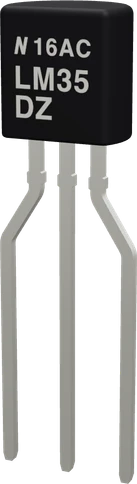
The LM35 is an analog temperature sensor whose output rises 10 mV for every °C, so it reads 250 mV at 25 °C and needs no calibration (TI LM35 datasheet, p. 1). Power +VS from 4 V to 30 V, tie GND to ground, and wire VOUT to an analog input; temperature in °C is the output voltage times 100 (pp. 1, 4). Wired this basic way, with no negative supply, it reads from 2 °C upward (p. 1).
The LM35 is a three-lead precision temperature sensor from Texas Instruments. Its output voltage is directly proportional to the temperature in Celsius at 10 mV/°C, with 0 mV at 0 °C, so unlike a Kelvin-scaled sensor there is no large offset to subtract (TI datasheet, p. 1). A reading of 0.25 V means 25 °C; 1.00 V means 100 °C.
It runs from 4 V to 30 V and draws about 56 µA at 5 V, so it barely warms itself: TI quotes 0.08 °C of self-heating in still air (pp. 1, 10). The hobby part is the LM35DZ, the LM35D grade in a TO-92 package, specified from 0 °C to 100 °C with ±1.5 °C maximum error at 25 °C and ±2 °C at the ends of its range (pp. 4, 9). The LM35 and LM35A grades extend the rating to -55 °C to 150 °C (p. 4).
The output stage can only source current; it sinks about 1 µA (p. 13). In the basic single-supply circuit that limits the range to 2 °C and above, because the output cannot go below ground. Reading below 0 °C needs a negative supply and a pull-down resistor to it (p. 1), which is why projects that must read below freezing usually choose a TMP36 instead.
LM35 Temperature Sensor pinout
| Pin | Function | Type |
|---|---|---|
| VCC | 1 +VS (4-30 V)4 to 30 V | power in |
| VOUT | ADC 10 mV/°C1.5 V | output |
| GND | 3 GND | power in |
How to wire the LM35 Temperature Sensor
Pin by pin, for the board you have.
| LM35 Temperature Sensor | Arduino Uno | Note |
|---|---|---|
| VCC | 5V | |
| VOUT | A0 | |
| GND | GND |
| LM35 Temperature Sensor | ESP32 DevKit V1 | Note |
|---|---|---|
| VCC | VIN | |
| VOUT | GPIO33 (D33) | |
| GND | GND |
- VCC is on VIN, which gives about 5 V only while the board is powered from USB.
| LM35 Temperature Sensor | Raspberry Pi Pico | Note |
|---|---|---|
| VCC | VBUS | |
| VOUT | GP28 | |
| GND | GND |
- VCC is on VBUS, which gives about 5 V only while the board is powered from USB.
LM35 Temperature Sensor code
Every example here compiles for its board.
// LM35 Temperature Sensor on Arduino Uno: wiring and a free simulation at https://www.tinkered.ai/components/lm35
const int VOUT_PIN = A0;          // LM35 VOUT
const float ADC_VREF = 1.1;       // analogReference(INTERNAL): the Uno's 1.1 V reference
const float ADC_STEPS = 1024.0;   // 10-bit ADC

void setup() {
  Serial.begin(9600);
  analogReference(INTERNAL);      // 0.1 °C steps, up to 110 °C
  analogRead(VOUT_PIN);           // the first reading after a reference change is discarded
  delay(10);
}

void loop() {
  long sum = 0;
  for (int i = 0; i < 8; i++) sum += analogRead(VOUT_PIN);
  float volts = (sum / 8.0) * ADC_VREF / ADC_STEPS;
  float tempC = volts * 100.0;              // 10 mV per °C, 0 V at 0 °C
  Serial.print("Temperature: ");
  Serial.print(tempC, 1);
  Serial.println(" C");
  delay(1000);
}
Before you wire it
- VCC to 5 V, always, on every board: an Uno's, Nano's, Mega's or R4's 5V, an ESP32 or ESP32-C3 board's 5V/VIN, a Pico's VBUS (or VSYS), a NodeMCU's VIN.
- GND to GND, VOUT to an ANALOG input: A0-A5 on an Uno, Nano or UNO R4, A0-A15 on a Mega, GP26-GP28 on a Pico, A0 on an ESP8266 NodeMCU, an ADC1 pin on an ESP32 (GPIO32-39; GPIO0-4 on a C3, GPIO1-10 on an S3).
- Convert with the board's analog reference and resolution: volts = raw * VREF / STEPS, then °C = volts * 100.
- Average 8 to 16 readings: one step of a 5 V Uno is 4.9 mV, half a degree.
- Power it from at least 4 V
- No swapping +VS and GND: turned round, it gets hot and is destroyed.
- No powering it from a 3.3 V pin (it needs 4 V at least).
- No pull-up or pull-down resistor, or LED, on VOUT.
- No digital pin for VOUT.
- (ESP32) NO ADC2 pin (GPIO 0/2/4/12-15/25-27) when the sketch uses Wi-Fi.
- Power +VS from 5 V. The LM35 needs at least 4 V (TI datasheet, p. 4), so a 3.3 V pin is out of spec; on an ESP32 or a Pico use the board's 5 V, VIN or VBUS pin.
- Its output stays low enough for a 3.3 V ADC: the LM35D is specified to 100 °C, which is 1.0 V, and even the full-range parts top out at 1.5 V at 150 °C (pp. 1, 4).
- Read VOUT on an analog input and convert with °C = volts × 100. On a 5 V Uno one ADC step is about 4.9 mV, half a degree, so average several readings or switch to the Uno's 1.1 V internal reference for about 0.1 °C steps.
- Keep loads off the output: it drives 50 pF on its own (p. 14). For long wires, isolate the cable with a 2 kΩ series resistor or add a damper of 75 Ω in series with 0.2 µF or 1 µF to ground (p. 14).
- In noisy settings TI recommends 0.1 µF from +VS to GND (p. 19).
Specifications
- Scale factor
- 10 mV/°C, 0 mV at 0 °C (250 mV at 25 °C)TI LM35 datasheet SNIS159H, p. 1
- Supply voltage
- 4 V to 30 V (35 V absolute maximum)TI LM35 datasheet SNIS159H, p. 4
- Quiescent current
- 56 µA typical, 80 µA max at 5 V, 25 °CTI LM35 datasheet SNIS159H, p. 10
- Accuracy (LM35D)
- ±0.6 °C typical, ±1.5 °C max at 25 °C; ±2 °C max over 0 to 100 °CTI LM35 datasheet SNIS159H, p. 9
- Specified range
- LM35D: 0 to 100 °C; LM35, LM35A: -55 to 150 °CTI LM35 datasheet SNIS159H, p. 4
- Basic circuit range
- 2 °C to 150 °C without a negative supplyTI LM35 datasheet SNIS159H, p. 1
- Self-heating
- 0.08 °C in still airTI LM35 datasheet SNIS159H, p. 1
- Output drive
- 0.1 Ω output impedance at 1 mA; sinks only about 1 µATI LM35 datasheet SNIS159H, pp. 1, 13
- Capacitive load
- 50 pF without precautionsTI LM35 datasheet SNIS159H, p. 14
- TO-92 pinout
- 1 +VS, 2 VOUT, 3 GND (bottom view)TI LM35 datasheet SNIS159H, p. 3
- Maximum supply voltage
- 35 V absolute (30 V recommended)TI LM35 datasheet, p. 4
- Interface
- Analog
- Dimensions
- 5.55 × 3.68 × 18.33 mm
- Weight
- 0.2 g
From the Texas Instruments's datasheet, published by Texas Instruments.
Common mistakes
Wiring it backwards
Seen from the bottom with the leads toward you, the TO-92 pins are 1 +VS, 2 VOUT, 3 GND (TI datasheet, p. 3). Swapping +VS and GND reverses the supply beyond its -0.2 V absolute limit (p. 4); the part heats up and fails.
Powering it from 3.3 V
The supply range starts at 4 V (p. 4). On 3.3 V the reading is outside the datasheet's guarantees. Use the board's 5 V pin; the output still stays under 1.5 V.
Expecting negative temperatures
In the basic circuit the output cannot go below ground, so the sensor reads from 2 °C upward (p. 1) and anything colder reads as about 0 °C. Use the negative-supply circuit on p. 1, or a TMP36, which has a 0.5 V offset.
Using the wrong reference in the conversion
volts = raw × VREF / steps must use the reference the ADC actually uses: 5.0 on a default Uno, 1.1 with analogReference(INTERNAL), 3.3 on an ESP32 or Pico. A mismatch scales every reading by the ratio, such as 4.5 times too high.
Hanging a long cable straight on the output
The LM35 drives only 50 pF without help (p. 14). A long cable can make it oscillate and read high or noisy; add the series resistor or the R-C damper TI shows.
LM35 Temperature Sensor questions
Can I use the LM35 with an ESP32 or a 3.3 V board?
Yes for the signal, no for the supply. The LM35 needs 4 V to 30 V on +VS (TI datasheet, p. 4), so power it from the board's 5 V or VIN pin. Its output is only 1.0 V at 100 °C for the LM35D (pp. 1, 4), safe for a 3.3 V ADC input without a divider.
How do I convert the LM35 reading to Celsius?
Convert the ADC reading to volts and multiply by 100, since the output is 10 mV/°C with 0 mV at 0 °C (TI datasheet, p. 1). On a 5 V Uno that is raw × 5.0 / 1024 × 100.
Why does my LM35 read 0 °C or wildly wrong values?
A steady 0 means VOUT sits at ground: check the pinout (1 +VS, 2 VOUT, 3 GND from the bottom, p. 3), the 5 V supply, and that VOUT goes to an analog pin. Values that are a fixed multiple off mean the code uses the wrong ADC reference. Noisy or high readings on a long cable call for the 2 kΩ series resistor or the 75 Ω plus 1 µF damper (p. 14).
Can the LM35 measure below 0 °C?
Not in the basic circuit, which covers 2 °C to 150 °C (TI datasheet, p. 1). With a negative supply and a resistor R1 = -VS / 50 µA from VOUT to it, the output goes negative, -550 mV at -55 °C (p. 1). The LM35DZ itself is only specified from 0 °C to 100 °C (p. 4).
LM35 vs TMP36: which should I use?
Both output 10 mV/°C. The LM35 has no offset (0 mV at 0 °C) and the LM35D is ±1.5 °C max at 25 °C (TI datasheet, pp. 1, 9), but it needs 4 V or more. The TMP36 adds a 0.5 V offset so it reads down to -40 °C on a single 2.7 V to 5.5 V supply (ADI TMP35/36/37 datasheet Rev. F, pp. 1, 8), with ±3 °C max at 25 °C for the TO-92 part (pp. 3, 19). Choose the LM35 for accuracy on 5 V, the TMP36 for 3.3 V boards or sub-zero readings.
How accurate is the LM35DZ?
The LM35D grade is ±0.6 °C typical and ±1.5 °C max at 25 °C, and ±2 °C max at the ends of its 0 to 100 °C range (TI datasheet, p. 9). Your ADC's resolution adds to that: a 10-bit, 5 V reading steps about half a degree.
Build something with the LM35 Temperature Sensor
- Build this
Room thermometer
Show the temperature on an LCD or OLED, averaged over a few seconds for a steady reading.
- Build this
Fan controller
Switch a fan through a MOSFET or relay when an enclosure passes a set temperature.
- Build this
Temperature data logger
Record readings to an SD card or the serial monitor to chart a day's temperature.
- Build this
Over-temperature alarm
Sound a buzzer when a motor, battery pack or heatsink runs too hot.
This page as plain Markdown, for ChatGPT, Claude or your own agent. /components/lm35.md