IRLB8721
A 30 V, 62 A logic-level N-channel MOSFET in TO-220, the usual low-side switch for 12 V LED strips, motors and solenoids from a GPIO.
- Drain-source voltage30 V
- Gate-source voltage±20 V maximum
- Continuous drain current62 A at TC = 25 °C, 44 A at TC = 100 °C (VGS = 10 V); 250 A pulsed
- On-resistance6.5 mOhm typ, 8.7 mOhm max at VGS = 10 V; 13.1 mOhm typ, 16 mOhm max at VGS = 4.5 V
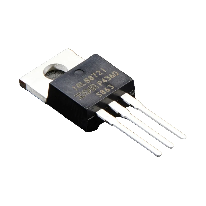
The IRLB8721 is a 30 V N-channel MOSFET rated 62 A with the case at 25 °C, with an on-resistance of 8.7 mOhm at 10 V gate drive and 16 mOhm at 4.5 V (IRLB8721PbF datasheet PD-97390, pp. 1, 2). Its gate threshold is 1.35 V to 2.35 V (p. 2), so a 5 V pin turns it fully on and a 3.3 V pin turns it on well enough for moderate loads. Put the load between the supply and the drain, the source to ground, and a 10 kOhm pull-down on the gate.
A MOSFET switches by voltage, not current: the gate draws only a brief charging current (7.6 nC typical gate charge, datasheet p. 1), and once on, the channel behaves like a few milliohms. That is why the IRLB8721 runs a 12 V LED strip or a pump from a GPIO with almost no heat, where a TIP120 Darlington would lose a volt or two.
It is a logic-level part: the datasheet guarantees 16 mOhm or less at 4.5 V on the gate (p. 2), which a 5 V Arduino provides. Adafruit lists the threshold below 2.5 V and drives it from 3.3 V boards (Adafruit #355). Note that the datasheet gives no on-resistance at 3.3 V, so on an ESP32 or Pico plan for a few amps and check how warm it gets, or drive the gate at 5 V.
Its limits are 30 V between drain and source and ±20 V on the gate (datasheet, p. 1). In free air the TO-220 has 62 °C/W from junction to ambient (p. 1), so about 2 W of dissipation is the practical limit without a heat sink, as Adafruit also notes.
IRLB8721 pinout
| Pin | Function | Type |
|---|---|---|
| G | Gate±20 V max; fully on at 4.5 V and above | input |
| D | DrainUp to 30 V | open collector |
| S | Source | passive |
How to wire the IRLB8721
Pin by pin, for the board you have.
| IRLB8721 | Arduino Uno | Note |
|---|---|---|
| G | D9 | Through 100 ohm; 10 kOhm from gate to GND. |
| S | GND | Also to the 12 V supply's negative. |
| D | LED strip - | LED strip + to the 12 V supply +. For a motor or solenoid add a flyback diode across the load, cathode to +12 V. |
- Keep the 12 V supply off the Uno's pins; only the grounds join, at the source.
- Keep the load supply under 30 V.
| IRLB8721 | ESP32 DevKit V1 | Note |
|---|---|---|
| G | GPIO25 (D25) | Through 100 ohm; 10 kOhm from gate to GND. |
| S | GND | Also to the 12 V supply's negative. |
| D | LED strip - | Strip + to 12 V. Flyback diode across inductive loads. |
- At 3.3 V on the gate the datasheet guarantees no on-resistance; keep loads to a few amps or drive the gate at 5 V through a gate driver, and check the MOSFET stays cool.
- The 10 kOhm pull-down keeps the load off while the ESP32 boots.
| IRLB8721 | Raspberry Pi Pico | Note |
|---|---|---|
| G | GP15 | Through 100 ohm; 10 kOhm from gate to GND. |
| S | GND | Also to the 12 V supply's negative. |
| D | LED strip - | Strip + to 12 V. Flyback diode across inductive loads. |
- With a 3.3 V gate, keep loads to a few amps and check the temperature; the datasheet specifies on-resistance only from 4.5 V up.
- Keep the 12 V supply away from VSYS and VBUS.
IRLB8721 code
Every example here compiles for its board.
// IRLB8721 on Arduino Uno: wiring and a free simulation at https://www.tinkered.ai/components/irlb8721
// IRLB8721 low-side switch on an Arduino Uno: gate via 100 ohm from D9, 10k pull-down,
// 12 V LED strip between +12 V and the drain. Fades the strip up and down.
const int GATE_PIN = 9;

void setup() {
  Serial.begin(115200);
  pinMode(GATE_PIN, OUTPUT);
  Serial.println("IRLB8721 LED strip fader");
}

void loop() {
  for (int d = 0; d <= 255; d += 5) { analogWrite(GATE_PIN, d); delay(20); }
  Serial.println("Full brightness");
  delay(1000);
  for (int d = 255; d >= 0; d -= 5) { analogWrite(GATE_PIN, d); delay(20); }
  Serial.println("Off");
  delay(1000);
}
// IRLB8721 on ESP32 DevKit V1: wiring and a free simulation at https://www.tinkered.ai/components/irlb8721
// IRLB8721 low-side switch on an ESP32 DevKit V1: gate via 100 ohm from GPIO25, 10k pull-down,
// 12 V LED strip between +12 V and the drain. Fades the strip up and down.
const int GATE_PIN = 25;

void setup() {
  Serial.begin(115200);
  pinMode(GATE_PIN, OUTPUT);
  analogWrite(GATE_PIN, 0);
  Serial.println("IRLB8721 LED strip fader");
}

void loop() {
  for (int d = 0; d <= 255; d += 5) { analogWrite(GATE_PIN, d); delay(20); }
  Serial.println("Full brightness");
  delay(1000);
  for (int d = 255; d >= 0; d -= 5) { analogWrite(GATE_PIN, d); delay(20); }
  Serial.println("Off");
  delay(1000);
}
// IRLB8721 on Raspberry Pi Pico: wiring and a free simulation at https://www.tinkered.ai/components/irlb8721
// IRLB8721 low-side switch on a Raspberry Pi Pico (arduino-pico): gate via 100 ohm from GP15,
// 10k pull-down, 12 V LED strip between +12 V and the drain. Fades the strip up and down.
const int GATE_PIN = 15;

void setup() {
  Serial.begin(115200);
  analogWriteRange(255);
  pinMode(GATE_PIN, OUTPUT);
  analogWrite(GATE_PIN, 0);
  Serial.println("IRLB8721 LED strip fader");
}

void loop() {
  for (int d = 0; d <= 255; d += 5) { analogWrite(GATE_PIN, d); delay(20); }
  Serial.println("Full brightness");
  delay(1000);
  for (int d = 255; d >= 0; d -= 5) { analogWrite(GATE_PIN, d); delay(20); }
  Serial.println("Off");
  delay(1000);
}
Before you wire it
- Wire it low-side: load from the supply's + to the drain, source to ground, grounds joined with your board.
- Fit a 10 kOhm resistor from gate to source so the load stays off while the board boots or resets.
- Fit a flyback diode across motors, solenoids and relay coils.
- Estimate the heat as I² x RDS(on): at 16 mOhm (4.5 V gate, datasheet p. 2) 10 A means 1.6 W, near the free-air limit of about 2 W (Adafruit #355).
- Never exceed 30 V drain to source (datasheet, p. 1), including spikes from inductive loads without a diode.
- Never exceed ±20 V on the gate (datasheet, p. 1).
- Never wire the load between the source and ground (high side): the gate would need to rise above the supply to turn it on.
- Never trust the 62 A rating without a heat sink: it assumes the case held at 25 °C (datasheet, p. 1).
- The 100 ohm gate resistor limits the brief current that charges the gate (7.6 nC typical, datasheet p. 1) and damps ringing; the 10 kOhm pull-down discharges it when the pin floats.
- At 4.5 V gate drive the channel is 16 mOhm or less (datasheet, p. 2), so a 5 V Uno pin switches 5 A with about 0.4 W of loss.
- The threshold of 1.35 V to 2.35 V (datasheet, p. 2) is where it starts to conduct, not where it is fully on; with a 3.3 V gate the resistance is higher than the 4.5 V figure.
- PWM at the default 490 Hz to 1 kHz works well for LED strips and motors; the low gate charge keeps switching losses small.
- For several channels of LED strip (RGB), use one MOSFET per colour, each with its own gate resistor and pull-down.
Specifications
- Drain-source voltage
- 30 VIRLB8721PbF datasheet PD-97390, p. 1
- Gate-source voltage
- ±20 V maximumIRLB8721PbF datasheet PD-97390, p. 1
- Continuous drain current
- 62 A at TC = 25 °C, 44 A at TC = 100 °C (VGS = 10 V); 250 A pulsedIRLB8721PbF datasheet PD-97390, p. 1
- On-resistance
- 6.5 mOhm typ, 8.7 mOhm max at VGS = 10 V; 13.1 mOhm typ, 16 mOhm max at VGS = 4.5 VIRLB8721PbF datasheet PD-97390, p. 2
- Gate threshold
- 1.35 V to 2.35 V (1.80 V typ)IRLB8721PbF datasheet PD-97390, p. 2
- Total gate charge
- 7.6 nC typicalIRLB8721PbF datasheet PD-97390, p. 1
- Thermal resistance
- 62 °C/W junction to ambient, 2.3 °C/W junction to caseIRLB8721PbF datasheet PD-97390, p. 1
- Power without heat sink
- About 2 W at room temperatureAdafruit N-channel power MOSFET (#355) product page
From the IRLB8721PbF HEXFET Power MOSFET datasheet, PD-97390, published by Infineon (International Rectifier).
Common mistakes
No gate pull-down
A floating gate holds whatever charge it had, so the LED strip or pump can switch on at power-up or stay half on. A 10 kOhm resistor from gate to source fixes it.
Expecting 62 A on a breadboard
The 62 A rating assumes a case held at 25 °C (datasheet, p. 1). In free air the TO-220 handles about 2 W (Adafruit #355), and breadboard contacts melt long before 62 A.
Using it as a high-side switch
With the load on the source side, the source rises toward the supply and the gate-source voltage collapses, so the MOSFET never fully turns on. Keep it on the low side, or use a P-channel MOSFET for high-side switching.
Motor without a flyback diode
When the MOSFET turns off, the motor's inductance drives the drain above 30 V (datasheet, p. 1). A diode across the motor, cathode to the positive supply, protects it.
IRLB8721 questions
Can an ESP32 or Raspberry Pi Pico drive the IRLB8721?
Yes for moderate loads: its threshold is at most 2.35 V (datasheet, p. 2) and Adafruit drives it from 3.3 V (#355). The datasheet only guarantees on-resistance from 4.5 V, so for loads of many amps from a 3.3 V board use a gate driver or check the temperature.
IRLB8721 or IRLZ44N?
Both are logic-level TO-220 MOSFETs. The IRLB8721 has lower on-resistance (16 mOhm max at 4.5 V, datasheet p. 2) and a smaller gate charge, but stops at 30 V; the IRLZ44N handles 55 V. For 12 V and 24 V strips either works; above 24 V take the IRLZ44N.
IRLB8721 or TIP120 for a 12 V LED strip?
The IRLB8721: it loses a few milliohms instead of the TIP120's 1 V to 2 V, so it stays cool at several amps. The TIP120 is fine below about 1 A.
What is the IRLB8721 pinout?
Facing the printed side, leads down: gate, drain, source from left to right, with the tab on the drain (TO-220AB).
Build something with the IRLB8721
- Build this
LED strip dimmer
Fade a 12 V single-colour LED strip from a knob or a schedule.
- Build this
RGB strip controller
Mix colours on a 12 V RGB strip with three MOSFETs.
- Build this
Plant watering pump
Run a 12 V pump when soil gets dry.
This page as plain Markdown, for ChatGPT, Claude or your own agent. /components/irlb8721.md