INMP441 I2S Microphone
A 3.3 V MEMS microphone that sends 24-bit digital audio straight to an ESP32 or STM32 over I2S, no ADC or codec needed.
- Supply (VDD)1.62 V to 3.63 V; absolute maximum 3.63 V
- Supply current1.4 mA typ at 1.8 V, 2.2 mA typ at 3.3 V (normal mode)
- Sensitivity-26 dBFS (-29 to -23) at 94 dB SPL, 1 kHz
- Signal-to-noise ratio61 dBA
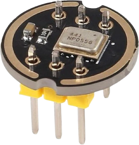
The INMP441 is an omnidirectional MEMS microphone with a 24-bit I2S output that runs on 1.62 V to 3.63 V and reads -26 dBFS at 94 dB SPL, flat from 60 Hz to 15 kHz (InvenSense DS-INMP441-00, pp. 1, 4). Wire VDD to 3.3 V, GND to GND, L/R to GND for the left channel, and SCK, WS and SD to an I2S port configured for 32-bit slots, 64 bit clocks per frame (p. 11). It needs an I2S peripheral, so it works on an ESP32 or STM32 but not on an Arduino Uno.
The INMP441 packs a MEMS sensor, signal conditioning, an ADC, anti-aliasing filters and an industry-standard 24-bit I2S interface into a 4.72 × 3.76 × 1 mm bottom-port package (InvenSense DS-INMP441-00, p. 1). Because the audio leaves the chip already digital, it connects straight to a microcontroller's I2S port with no analog front end, no codec and no noisy ADC readings, which makes it the usual microphone for ESP32 voice, sound-level and audio-streaming projects. Makers buy it on a small round breakout with six pins: L/R, WS, SCK, GND, VDD and SD.
The microcontroller is the I2S master: it drives the bit clock SCK (0.5 to 3.2 MHz) and the word select WS (7.8 to 50 kHz, which is the sample rate), and the microphone answers on SD (p. 5). Each word is 24-bit two's complement, MSB first, and the frame must hold exactly 64 SCK cycles, 32 per channel (p. 11). L/R picks the channel the microphone drives: low for left, high for right (p. 8), so two microphones can share one SD line as a stereo pair, one on each setting (p. 11).
It reads -26 dBFS for a 94 dB SPL tone, with a 61 dBA signal-to-noise ratio, a -87 dBFS noise floor and a 120 dB SPL maximum input (p. 4). After power-up its output is zero for the first 2^18 SCK cycles, 85 ms at 3.072 MHz (p. 10), so discard the first reads. The supply is the one thing to get right: 3.63 V is both the top of its range and its absolute maximum (pp. 4, 6), so 5 V destroys it.
INMP441 I2S Microphone pinout
| Pin | Function | Type |
|---|---|---|
| LR | Digital | input |
| WS | I2S WS / LRCLK: the frame clock, left slot while low | input |
| SCK | I2S SCK / BCLK: the bit clock, exactly 64 x WS | input |
| GND | GND | power in |
| VDD | VDD (1.8-3.3V)1.62–3.3 V | power in |
| SD | I2S SD: serial data out (to the MCU's I2S data in), hi-Z outside its slot | tri state |
How to wire the INMP441 I2S Microphone
Pin by pin, for the board you have.
| INMP441 I2S Microphone | ESP32 DevKit V1 | Note |
|---|---|---|
| VDD | 3V3 | |
| GND | GND | |
| LR | GND | |
| SCK | GPIO26 (D26) | |
| WS | GPIO25 (D25) | |
| SD | GPIO33 (D33) |
| INMP441 I2S Microphone | XIAO ESP32-S3 Sense | Note |
|---|---|---|
| VDD | 3V3 | |
| GND | GND | |
| LR | GND | |
| SCK | D1 | |
| WS | D0 | |
| SD | D2 |
INMP441 I2S Microphone code
Every example here compiles for its board.
// INMP441 I2S Microphone on ESP32 DevKit V1: wiring and a free simulation at https://www.tinkered.ai/components/inmp441-i2s-mic
#include <driver/i2s.h>
void setup() {
  Serial.begin(115200);
  i2s_config_t cfg = {};
  cfg.mode = (i2s_mode_t) (I2S_MODE_MASTER | I2S_MODE_RX);
  cfg.sample_rate = 16000;
  cfg.bits_per_sample = I2S_BITS_PER_SAMPLE_32BIT;
  cfg.channel_format = I2S_CHANNEL_FMT_ONLY_RIGHT;  // L/R on GND sends the left slot (WS low); with 32-bit samples the classic ESP32's legacy driver stores that slot as ONLY_RIGHT
  cfg.communication_format = I2S_COMM_FORMAT_STAND_I2S;
  cfg.dma_buf_count = 4;
  cfg.dma_buf_len = 256;
  i2s_driver_install(I2S_NUM_0, &cfg, 0, NULL);
  i2s_pin_config_t pins = {};
  pins.mck_io_num = I2S_PIN_NO_CHANGE;
  pins.bck_io_num = 26;                 // GPIO26 -> SCK
  pins.ws_io_num = 25;                  // GPIO25 -> WS
  pins.data_out_num = I2S_PIN_NO_CHANGE;
  pins.data_in_num = 33;                // GPIO33 <- SD
  i2s_set_pin(I2S_NUM_0, &pins);
}
void loop() {
  static int32_t buf[256];
  size_t got;
  i2s_read(I2S_NUM_0, buf, sizeof(buf), &got, portMAX_DELAY);
  double sum = 0;
  for (size_t i = 0; i < got / 4; i++) { double s = (buf[i] >> 8) / 8388608.0; sum += s * s; }
  Serial.printf("level %.1f dBFS\n", 10 * log10(sum / (got / 4) + 1e-12));
}
Before you wire it
- An I2S microphone: it sends digital audio, not an analog voltage. Never on an analog pin, never on an Arduino Uno, Nano or UNO R4 (no I2S). On the XIAO ESP32-S3 Sense, the board's own PDM microphone needs no part at all.
- Power VDD from 3V3 (1.62-3.63 V). 5 V destroys it (absolute maximum 3.63 V). GND to GND.
- L/R must not float: GND = left slot (WS low), 3V3 = right slot. Tie it to GND for one microphone.
- Three signal wires: SCK (bit clock, from the MCU), WS (word select, from the MCU), SD (serial data, the microphone's output, to the MCU's I2S data in). The MCU is the I2S master.
- The board (14 mm round, black): two rows of three pins 0.3" apart, straddling the breadboard's gap like a DIP-6, numbered round the board. One row reads L/R, WS, SCK, the other GND, VDD, SD, so SD sits across from SCK and GND across from L/R. Plugged in, the INMP441's silver lid faces up; its sound port is a hole through the board on the label side.
- Use the board's suggested I2S pins (the board card lists them): DevKits SCK=IO26, WS=IO25, SD → IO33; XIAO ESP32-S3 SCK=D1, WS=D0, SD → D2; Freenove S3 SCK=IO21, WS=IO47, SD → IO41. SD may go on an input-only pin (IO34-IO39); SCK and WS may not.
- 32-bit samples only: 24-bit data in 32-bit slots, 64 bit clocks per frame (the datasheet requires it). Shift each 32-bit word right by 8 for the 24-bit sample. 16-bit samples give 32 clocks a frame and the microphone stays silent.
- Clocks: SCK 0.5-3.2 MHz, WS 7.8-50 kHz (16 kHz for speech, 44.1/48 kHz for music).
- Two INMP441s share SCK, WS and SD as a stereo pair: one L/R to GND, the other to 3V3.
- It outputs zeros for its first 2^18 bit clocks (256 ms at 16 kHz) after power-up or a clock start: discard those reads.
- Levels: -26 dBFS at 94 dB SPL (a loud voice at 30 cm), 120 dB SPL maximum, noise floor -87 dBFS, 60 Hz low corner. Compute RMS in dBFS over a block; never compare single raw samples.
- Do not power it from 5V or VIN.
- Do not leave L/R unconnected.
- Do not read it with analogRead(), or with I2S_BITS_PER_SAMPLE_16BIT.
- Do not put SCK or WS on an input-only pin (IO34-IO39 on the DevKits).
- Do not give two microphones on one SD line the same L/R: they drive the same slot and fight.
- Power VDD from 3.3 V only. The supply range is 1.62 V to 3.63 V and the absolute maximum is 3.63 V (InvenSense DS-INMP441-00, pp. 4, 6): never wire it to 5 V or VIN. InvenSense asks for 0.1 µF of decoupling at VDD (p. 8).
- Tie L/R to GND for the left channel or to VDD for the right channel (p. 8); never leave it floating. For stereo, put two microphones on the same SCK, WS and SD with opposite L/R settings (p. 11).
- SCK and WS are outputs of the microcontroller (the I2S master); SD is the microphone's output into the I2S data-in pin. Its digital inputs read high at 0.7 × VDD (p. 5), so drive them from a 3.3 V microcontroller.
- SD tri-states between words; InvenSense recommends a 100 kΩ pull-down on the SD line to discharge it while no microphone is driving (pp. 8, 11).
- Configure the I2S port for 32-bit samples so each frame carries the 64 SCK cycles the microphone requires (p. 11), and shift each 32-bit word right by 8 to get the 24-bit sample.
- Do not run SCK and WS into the microphone while VDD is off: InvenSense warns this keeps its ESD diodes on and can hurt long-term reliability (p. 10).
Specifications
- Supply (VDD)
- 1.62 V to 3.63 V; absolute maximum 3.63 VInvenSense DS-INMP441-00 Rev 1.1, pp. 4, 6
- Supply current
- 1.4 mA typ at 1.8 V, 2.2 mA typ at 3.3 V (normal mode)InvenSense DS-INMP441-00 Rev 1.1, p. 4
- Sensitivity
- -26 dBFS (-29 to -23) at 94 dB SPL, 1 kHzInvenSense DS-INMP441-00 Rev 1.1, p. 4
- Signal-to-noise ratio
- 61 dBAInvenSense DS-INMP441-00 Rev 1.1, p. 4
- Frequency response
- 60 Hz to 15 kHz (-3 dB points)InvenSense DS-INMP441-00 Rev 1.1, p. 4
- Maximum acoustic input
- 120 dB SPL peakInvenSense DS-INMP441-00 Rev 1.1, p. 4
- Data format
- I2S, 24-bit two's complement, MSB first, 64 SCK per stereo frameInvenSense DS-INMP441-00 Rev 1.1, p. 11
- Clocks
- SCK 0.5 to 3.2 MHz, WS 7.8 to 50 kHzInvenSense DS-INMP441-00 Rev 1.1, p. 5
- Start-up
- Zero output for 2^18 SCK cycles (85 ms at 3.072 MHz)InvenSense DS-INMP441-00 Rev 1.1, p. 10
- Package
- 4.72 × 3.76 × 1 mm, bottom port, -40 to +85 °CInvenSense DS-INMP441-00 Rev 1.1, p. 1
- Supply voltage
- 1.62–3.3 V
- Maximum supply voltage
- 3.63 V
- Interface
- I2S
- Dimensions
- 14 × 14 × 4.2 mm
- Weight
- 1 g
From the Generic (TDK InvenSense INMP441)'s datasheet, published by Generic (TDK InvenSense INMP441).
Common mistakes
Powering it from 5 V
The INMP441's absolute maximum supply is 3.63 V (InvenSense DS-INMP441-00, p. 6). 5 V on VDD destroys it. Use the board's 3V3 pin.
Using 16-bit I2S samples
The microphone requires 64 SCK cycles per stereo frame (p. 11). A 16-bit configuration sends only 32 clocks per frame and the data comes back as zeros. Set the I2S driver to 32-bit samples and keep the top 24 bits.
Leaving L/R floating
L/R selects which half of the frame the microphone drives: low for left, high for right (p. 8). Floating, the channel is undefined and your code reads the wrong slot or noise. Tie it to GND for a single microphone.
Trying it on an Arduino Uno or Nano
The INMP441 needs an I2S receiver. Classic AVR boards have no I2S peripheral, so the microphone cannot be read there; use an ESP32, ESP32-S3, an STM32 F4 or a Raspberry Pi Pico with a PIO I2S library.
Reading the first samples as silence or a fault
The output is zero for the first 2^18 SCK cycles after power-up, 85 ms at 3.072 MHz (p. 10), which is 256 ms at a 16 kHz sample rate. Throw away the first buffers before measuring levels.
INMP441 I2S Microphone questions
Can I power the INMP441 from 5 V?
No. Its supply range is 1.62 V to 3.63 V and 3.63 V is also the absolute maximum (InvenSense DS-INMP441-00, pp. 4, 6). Power it from the 3.3 V pin of an ESP32, ESP32-S3 or STM32 board, whose I2S pins are 3.3 V as well.
Why does my INMP441 only output zeros?
The usual causes are 16-bit samples (it needs 64 SCK cycles per frame, p. 11), L/R floating or tied to the side your code does not read (p. 8), SD wired to a different pin than the sketch's data-in, or reading during the first 2^18 clock cycles after start-up (85 ms at 3.072 MHz, p. 10). If one channel stays empty, read the other slot: drivers differ in which slot they label left.
How do I wire the INMP441 to an ESP32?
VDD to 3V3, GND to GND, L/R to GND, SCK to the I2S bit-clock pin, WS to the word-select pin and SD to the I2S data-in pin. On an ESP32 DevKit, SCK on GPIO26, WS on GPIO25 and SD on GPIO33 is a common choice; configure the driver as master receive with 32-bit samples (p. 11).
What sample rate can the INMP441 record at?
WS is the sample rate and may run from 7.8 kHz to 50 kHz, with SCK at 64 times WS within 0.5 to 3.2 MHz (DS-INMP441-00, pp. 5, 11). 16 kHz is enough for speech; 44.1 or 48 kHz suits music within its 60 Hz to 15 kHz response (p. 4).
INMP441 vs KY-038: which microphone should I use?
The INMP441 for real audio: it delivers calibrated 24-bit samples over I2S, -26 dBFS at 94 dB SPL and 61 dBA SNR (DS-INMP441-00, p. 4). The KY-038 is an electret capsule with a comparator and an analog output, good for detecting a clap or a loud noise on any board with an ADC, but not for recording or measuring sound levels.
How do I turn INMP441 samples into decibels?
Compute the RMS of a block of samples relative to full scale, in dBFS. The microphone reads -26 dBFS for a 94 dB SPL tone (p. 4), so sound pressure level is roughly dBFS + 120 for a sine wave; InvenSense defines 0 dBFS as a sine whose peak touches full scale (p. 12).
Build something with the INMP441 I2S Microphone
- Build this
Voice assistant or wake-word device
Stream 16 kHz audio from an ESP32-S3 to a speech-to-text service or an on-device model.
- Build this
Sound level meter
Compute RMS dBFS over short blocks and show a live noise level on an OLED.
- Build this
Wi-Fi audio streamer
Send the microphone's samples over UDP or WebSocket to a computer for recording.
- Build this
Stereo recorder
Pair two INMP441s on one I2S bus, one set to left and one to right, and record to a microSD card.
- Build this
Clap or noise trigger
Switch a light or log an event when the level crosses a threshold.
This page as plain Markdown, for ChatGPT, Claude or your own agent. /components/inmp441-i2s-mic.md