INMP441 I2S Microphone with an ESP32 DevKit V1
A 3.3 V MEMS microphone that sends 24-bit digital audio straight to an ESP32 or STM32 over I2S, no ADC or codec needed.
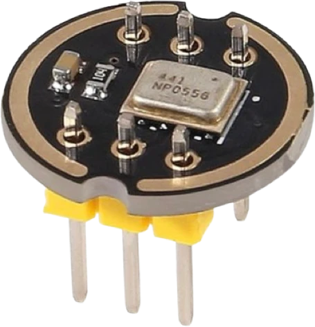
On the ESP32 DevKit V1 the INMP441 runs from 3V3, inside its 1.62 to 3.63 V range, with L/R on GND so it transmits in the left slot. The ESP32 is the I2S master: it drives SCK on GPIO26 and WS on GPIO25 and reads SD on GPIO33, three pins clear of the USB serial lines and of the pins the chip samples at boot.
Wiring the INMP441 I2S Microphone to the ESP32 DevKit V1
Pin by pin.
| INMP441 I2S Microphone | ESP32 DevKit V1 |
|---|---|
| VDD | 3V3 |
| GND | GND |
| LR | GND |
| SCK | GPIO26 (D26) |
| WS | GPIO25 (D25) |
| SD | GPIO33 (D33) |
What to know on the ESP32 DevKit V1
- With L/R on GND the microphone talks while WS is low, the left slot, yet the sketch asks for I2S_CHANNEL_FMT_ONLY_RIGHT. In ESP-IDF 4.4.7's legacy driver on the classic ESP32, 32 bit receive samples come out with the slots swapped, so ONLY_LEFT would store the half the microphone leaves empty and ONLY_RIGHT holds its audio.InvenSense DS-INMP441-00 Rev 1.1, p. 8; ESP-IDF v4.4.7 components/hal/i2s_hal.c (i2s_hal_rx_set_channel_style) and components/hal/esp32/include/hal/i2s_ll.h (i2s_ll_rx_set_chan_mod)
- At 16 kHz with 32 bit slots the ESP32 sends 64 SCK cycles per frame, a 1.024 MHz bit clock, inside the microphone's 0.5 to 3.2 MHz range. Switching to 16 bit samples would halve the cycles per frame, and the INMP441 needs 64, so it would stay silent.InvenSense DS-INMP441-00 Rev 1.1, pp. 5, 11
- After its clocks start the INMP441 outputs zeros for 2^18 SCK cycles, which at this 1.024 MHz clock is about 256 ms, so the first lines the sketch prints after a reset show silence whatever the room is doing.InvenSense DS-INMP441-00 Rev 1.1, p. 10
- SD only carries data into the ESP32, so it may move to an input only pin (GPIO34 to GPIO39); SCK and WS are outputs and may not. Keep all three off GPIO1 and GPIO3, the USB serial link, and off GPIO0, GPIO2, GPIO5, GPIO12 and GPIO15, which set the boot configuration.Espressif ESP32 Series Datasheet v5.3, pp. 14, 15, 22
- InvenSense recommends a 100 kOhm resistor from SD to GND: the microphone tristates SD during the slot it does not use, and the resistor discharges the line so that slot reads cleanly.InvenSense DS-INMP441-00 Rev 1.1, pp. 8, 11
INMP441 I2S Microphone code for the ESP32 DevKit V1
Compiled for esp32:esp32:esp32 on 2026-10-30.
// INMP441 I2S Microphone on ESP32 DevKit V1: wiring and a free simulation at https://www.tinkered.ai/components/inmp441-i2s-mic/esp32
#include <driver/i2s.h>
void setup() {
  Serial.begin(115200);
  i2s_config_t cfg = {};
  cfg.mode = (i2s_mode_t) (I2S_MODE_MASTER | I2S_MODE_RX);
  cfg.sample_rate = 16000;
  cfg.bits_per_sample = I2S_BITS_PER_SAMPLE_32BIT;
  cfg.channel_format = I2S_CHANNEL_FMT_ONLY_RIGHT;  // L/R on GND sends the left slot (WS low); with 32-bit samples the classic ESP32's legacy driver stores that slot as ONLY_RIGHT
  cfg.communication_format = I2S_COMM_FORMAT_STAND_I2S;
  cfg.dma_buf_count = 4;
  cfg.dma_buf_len = 256;
  i2s_driver_install(I2S_NUM_0, &cfg, 0, NULL);
  i2s_pin_config_t pins = {};
  pins.mck_io_num = I2S_PIN_NO_CHANGE;
  pins.bck_io_num = 26;                 // GPIO26 -> SCK
  pins.ws_io_num = 25;                  // GPIO25 -> WS
  pins.data_out_num = I2S_PIN_NO_CHANGE;
  pins.data_in_num = 33;                // GPIO33 <- SD
  i2s_set_pin(I2S_NUM_0, &pins);
}
void loop() {
  static int32_t buf[256];
  size_t got;
  i2s_read(I2S_NUM_0, buf, sizeof(buf), &got, portMAX_DELAY);
  double sum = 0;
  for (size_t i = 0; i < got / 4; i++) { double s = (buf[i] >> 8) / 8388608.0; sum += s * s; }
  Serial.printf("level %.1f dBFS\n", 10 * log10(sum / (got / 4) + 1e-12));
}
INMP441 I2S Microphone on the ESP32 DevKit V1: questions
Why does the ESP32 sketch read the right channel when L/R is on GND?
Because of how ESP-IDF 4.4.7's legacy I2S driver, used by arduino-esp32 2.0.17, maps 32 bit receive slots on the classic ESP32: ONLY_RIGHT is the setting that keeps the WS low slot, where a microphone with L/R on GND transmits (InvenSense, p. 8). On another core version or chip, test both settings while you speak and keep the one whose level moves.
Can I power the INMP441 from VIN on the ESP32?
No. Its absolute maximum supply is 3.63 V (InvenSense, p. 6), and VIN carries about 5 V on USB. Use 3V3, which also matches its input threshold of 0.7 x VDD on SCK and WS (p. 5).
How do I record stereo with two INMP441s on one ESP32?
Share SCK, WS and SD between both microphones, tie one L/R to GND and the other to 3V3 (InvenSense, p. 11), and change the driver to read both slots with I2S_CHANNEL_FMT_RIGHT_LEFT. Each frame then holds one sample from each microphone.
This guide as plain Markdown. /components/inmp441-i2s-mic/esp32.md