ILI9488 TFT 3.5"
A 3.5-inch 480 × 320 colour TFT on a red SPI module (MSP3520) driven by an ILI9488, with optional resistive touch and a microSD slot.
- Resolution480 × 320 pixels, 3.5-inch, 48.96 × 73.44 mm active area
- Module powerVCC 3.3 V to 5 V, about 0.62 W
- Logic level3.3 V TTL on all signal pins
- Controller suppliesIOVCC 1.65 V to 3.3 V, VCI 2.5 V to 3.3 V; inputs high from 0.7 × IOVCC
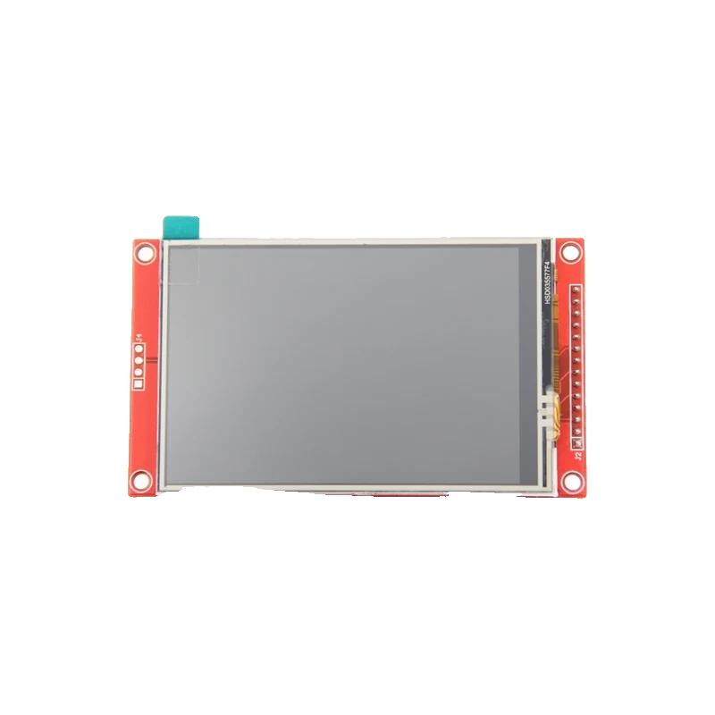
The 3.5-inch ILI9488 module is a 480 × 320 colour TFT on a 14-pin SPI header (display, touch and power); VCC takes 3.3 V to 5 V but every logic pin is 3.3 V TTL, and it draws about 0.62 W (LCDwiki MSP3520 page). Its ILI9488 accepts at most IOVCC + 0.3 V on its inputs and, over 4-wire SPI, takes only 18-bit (RGB 6-6-6) or 3-bit pixels (ILITEK ILI9488 Specification V100, pp. 121 to 122, 322). It wires straight to an ESP32 or a Pico, needs a 3.3 V buffer on an Uno, and runs with Arduino_GFX's Arduino_ILI9488_18bit driver.
This red 3.5-inch module is the big screen of the SPI world: 480 × 320 pixels from an ILI9488 that holds the whole frame in its own memory and supports 16.7 million colours (ILITEK ILI9488 Specification V100, p. 1). The MSP3520 version adds a resistive touch panel with its own SPI pins; the MSP3521 has no touch. Both carry a microSD slot (LCDwiki MSP3520 page).
Its quirk is the pixel format. Over 4-wire SPI the ILI9488 accepts 18-bit RGB 6-6-6 or 3-bit colour only, not the 16-bit RGB 5-6-5 that ILI9341 code sends (pp. 121 to 122). Each pixel therefore costs three bytes on the bus, which makes full-screen redraws slower than on smaller displays and is why ILI9341 libraries show garbage on it. Libraries with a dedicated ILI9488 driver, such as Arduino_GFX's Arduino_ILI9488_18bit, convert the colours for you.
Power and logic are separate questions. VCC accepts 3.3 V to 5 V through the module's regulator, while CS, RESET, DC, SDI, SCK and the touch lines are 3.3 V TTL (LCDwiki MSP3520 page), and the ILI9488's inputs are limited to IOVCC + 0.3 V (p. 322). Feed VCC from 5 V to spare the board's 3.3 V regulator; the module draws about 0.62 W, mostly backlight.
ILI9488 TFT 3.5" pinout
| Pin | Function | Type |
|---|---|---|
| VCC | Supply3.3 V to 5 V | power in |
| GND | Ground | power in |
| CS | LCD SPI CS (active low)3.3 V TTL | input |
| RESET | LCD reset (active low)3.3 V TTL | input |
| DC | Register / data select3.3 V TTL | input |
| SDI | SPI MOSI3.3 V TTL | input |
| SCK | SPI SCK3.3 V TTL | input |
| LED | Backlight (high = on) | input |
| SDO | SPI MISO | output |
| T_CLK | Touch SPI SCK | input |
| T_CS | Touch CS (active low) | input |
| T_DIN | Touch SPI MOSI | input |
| T_DO | Touch SPI MISO | output |
| T_IRQ | Touch interrupt (low when touched) | output |
How to wire the ILI9488 TFT 3.5"
Pin by pin, for the board you have.
| ILI9488 TFT 3.5" | Arduino Uno | Note |
|---|---|---|
| VCC | 5V | |
| GND | GND | |
| CS | D10 through a 74HC4050 buffer powered from 3.3 V | |
| RESET | D8 through the 74HC4050 | |
| DC/RS | D9 through the 74HC4050 | |
| SDI(MOSI) | D11 through the 74HC4050 | |
| SCK | D13 through the 74HC4050 | |
| LED | 3.3V |
- The ILI9488's inputs are limited to IOVCC + 0.3 V (ILITEK specification, p. 322): 5 V Uno signals need the buffer.
- An Uno redraws 480 × 320 × 3 bytes slowly; expect text and simple graphics rather than animation.
| ILI9488 TFT 3.5" | ESP32 DevKit V1 | Note |
|---|---|---|
| VCC | VIN (5 V) | |
| GND | GND | |
| CS | GPIO5 (D5) | |
| RESET | GPIO17 (TX2) | |
| DC/RS | GPIO16 (RX2) | |
| SDI(MOSI) | GPIO23 (D23) | |
| SCK | GPIO18 (D18) | |
| LED | 3V3 |
| ILI9488 TFT 3.5" | Raspberry Pi Pico | Note |
|---|---|---|
| VCC | VBUS (5 V from USB) | |
| GND | GND | |
| CS | GP17 | |
| RESET | GP20 | |
| DC/RS | GP21 | |
| SDI(MOSI) | GP19 | |
| SCK | GP18 | |
| LED | 3V3(OUT) |
- VBUS is 5 V only on USB power; on battery, feed VCC from VSYS or a separate supply.
ILI9488 TFT 3.5" code
Every example here compiles for its board.
// ILI9488 TFT 3.5" on Arduino Uno: wiring and a free simulation at https://www.tinkered.ai/components/ili9488-tft-3-5
// 3.5" ILI9488 SPI TFT on an Arduino Uno through a 74HC4050: CS D10, DC D9, RESET D8, SDI D11, SCK D13
#include <Arduino_GFX_Library.h>

Arduino_DataBus *bus = new Arduino_HWSPI(9 /* DC */, 10 /* CS */);
Arduino_GFX *gfx = new Arduino_ILI9488_18bit(bus, 8 /* RST */, 1 /* rotation: landscape */, false /* IPS */);

void setup() {
  Serial.begin(115200);
  if (!gfx->begin()) {
    Serial.println(F("ILI9488 init failed"));
    while (true) {}
  }
  gfx->fillScreen(RGB565_BLACK);
  gfx->fillRect(0, 0, 480, 60, RGB565_BLUE);
  gfx->setTextColor(RGB565_WHITE);
  gfx->setTextSize(4);
  gfx->setCursor(20, 15);
  gfx->print(F("ILI9488 3.5in"));
  Serial.println(F("Display ready"));
}

void loop() {
  static unsigned long seconds = 0;
  gfx->setTextColor(RGB565_YELLOW, RGB565_BLACK);
  gfx->setTextSize(6);
  gfx->setCursor(20, 140);
  gfx->print(seconds);
  gfx->print(F(" s "));
  Serial.print(F("Uptime: "));
  Serial.println(seconds);
  seconds++;
  delay(1000);
}
// ILI9488 TFT 3.5" on ESP32 DevKit V1: wiring and a free simulation at https://www.tinkered.ai/components/ili9488-tft-3-5
// 3.5" ILI9488 SPI TFT on an ESP32 DevKit V1: CS GPIO5, DC GPIO16, RESET GPIO17, SDI GPIO23, SCK GPIO18
#include <Arduino_GFX_Library.h>

Arduino_DataBus *bus = new Arduino_HWSPI(16 /* DC */, 5 /* CS */);
Arduino_GFX *gfx = new Arduino_ILI9488_18bit(bus, 17 /* RST */, 1 /* rotation: landscape */, false /* IPS */);

void setup() {
  Serial.begin(115200);
  if (!gfx->begin()) {
    Serial.println("ILI9488 init failed");
    while (true) { delay(100); }
  }
  gfx->fillScreen(RGB565_BLACK);
  gfx->fillRect(0, 0, 480, 60, RGB565_BLUE);
  gfx->setTextColor(RGB565_WHITE);
  gfx->setTextSize(4);
  gfx->setCursor(20, 15);
  gfx->print("ILI9488 3.5in");
  Serial.println("Display ready");
}

void loop() {
  static unsigned long seconds = 0;
  gfx->setTextColor(RGB565_YELLOW, RGB565_BLACK);
  gfx->setTextSize(6);
  gfx->setCursor(20, 140);
  gfx->printf("%lu s ", seconds);
  Serial.printf("Uptime: %lu s\n", seconds);
  seconds++;
  delay(1000);
}
// ILI9488 TFT 3.5" on Raspberry Pi Pico: wiring and a free simulation at https://www.tinkered.ai/components/ili9488-tft-3-5
// 3.5" ILI9488 SPI TFT on a Raspberry Pi Pico (arduino-pico): CS GP17, DC GP21, RESET GP20, SDI GP19, SCK GP18
#include <Arduino_GFX_Library.h>

Arduino_DataBus *bus = new Arduino_HWSPI(21 /* DC */, 17 /* CS */);
Arduino_GFX *gfx = new Arduino_ILI9488_18bit(bus, 20 /* RST */, 1 /* rotation: landscape */, false /* IPS */);

void setup() {
  Serial.begin(115200);
  if (!gfx->begin()) {
    Serial.println("ILI9488 init failed");
    while (true) { delay(100); }
  }
  gfx->fillScreen(RGB565_BLACK);
  gfx->fillRect(0, 0, 480, 60, RGB565_BLUE);
  gfx->setTextColor(RGB565_WHITE);
  gfx->setTextSize(4);
  gfx->setCursor(20, 15);
  gfx->print("ILI9488 3.5in");
  Serial.println("Display ready");
}

void loop() {
  static unsigned long seconds = 0;
  gfx->setTextColor(RGB565_YELLOW, RGB565_BLACK);
  gfx->setTextSize(6);
  gfx->setCursor(20, 140);
  gfx->print(seconds);
  gfx->print(" s ");
  Serial.print("Uptime: ");
  Serial.println(seconds);
  seconds++;
  delay(1000);
}
Before you wire it
- Use a driver written for the ILI9488 (Arduino_ILI9488_18bit, TFT_eSPI's ILI9488 setup or LovyanGFX): over SPI it accepts only 18-bit or 3-bit pixels (ILITEK specification, pp. 121 to 122).
- Keep every signal pin at 3.3 V: the module's logic is 3.3 V TTL (LCDwiki MSP3520 page).
- Power VCC from 5 V where available; the module draws about 0.62 W.
- Give the display, touch and SD card separate CS pins if you use all three.
- Never drive the module's signal pins straight from a 5 V Uno.
- Never expect ILI9341 libraries to work: they send 16-bit pixels the ILI9488 does not accept over SPI.
- Never exceed the 20 MHz write clock in the specification (p. 332) on long jumper wires.
- SDO (MISO) is only needed to read the display back; most sketches leave it unconnected (LCDwiki MSP3520 page).
- The touch controller has its own SPI pins (T_CLK, T_CS, T_DIN, T_DO, T_IRQ), which can share the board's SPI bus with a separate CS.
- LED is the backlight control: high is on, so tie it to 3.3 V or drive it from a PWM pin to dim (LCDwiki MSP3520 page).
- Three bytes per pixel means a full 480 × 320 frame is about 460 KB on the bus; ESP32 and RP2040 at tens of MHz redraw it many times faster than an Uno.
- A 74HC4050 hex buffer powered from 3.3 V covers CS, RESET, DC, SDI and SCK on a 5 V board.
Specifications
- Resolution
- 480 × 320 pixels, 3.5-inch, 48.96 × 73.44 mm active areaLCDwiki MSP3520 page, product parameters
- Module power
- VCC 3.3 V to 5 V, about 0.62 WLCDwiki MSP3520 page, product parameters
- Logic level
- 3.3 V TTL on all signal pinsLCDwiki MSP3520 page, product parameters
- Controller supplies
- IOVCC 1.65 V to 3.3 V, VCI 2.5 V to 3.3 V; inputs high from 0.7 × IOVCCILITEK ILI9488 Specification V100, p. 323
- Absolute maximum
- IOVCC 3.3 V; logic inputs -0.3 V to IOVCC + 0.3 VILITEK ILI9488 Specification V100, Table 41, p. 322
- SPI pixel formats
- 4-line SPI: 18-bit RGB 6-6-6 (262K colours) or 3-bit onlyILITEK ILI9488 Specification V100, pp. 121 to 122
- SPI write clock
- 50 ns minimum write cycle (20 MHz) on 4-line SPIILITEK ILI9488 Specification V100, p. 332
- Operating temperature
- -20 °C to 60 °C (module)LCDwiki MSP3520 page, product parameters
From the LCDwiki 3.5inch SPI Module ILI9488 (MSP3520) and ILITEK ILI9488 Specification V100, published by ILI Technology (ILI9488), module by LCDwiki.
Common mistakes
Using an ILI9341 library
ILI9341 code sends 16-bit RGB 5-6-5 pixels, which the ILI9488 does not accept on SPI (ILITEK specification, pp. 121 to 122); the screen stays white or shows noise. Use a library with an ILI9488 driver.
5 V logic from an Uno
VCC accepts 5 V, but the signal pins are 3.3 V TTL and the controller's inputs are limited to IOVCC + 0.3 V (p. 322). Buffer the lines through a 74HC4050 on 3.3 V.
White screen with the backlight on
A white screen means the backlight works but the controller is not initialised: check CS, DC and RESET against the code, and that the driver is ILI9488, not ILI9486 or ILI9341.
Powering it from a weak 3.3 V pin
At about 0.62 W the module needs well over 100 mA. Feed VCC from 5 V (VIN, VBUS or the Uno's 5V) rather than loading a small 3.3 V regulator.
ILI9488 TFT 3.5" questions
Is the 3.5-inch ILI9488 module 5 V compatible?
Its power pin is: VCC takes 3.3 V to 5 V. Its signals are not: they are 3.3 V TTL (LCDwiki MSP3520 page), and the ILI9488's inputs are limited to IOVCC + 0.3 V (ILITEK specification, p. 322).
Why does ILI9341 code not work on the ILI9488?
Over SPI the ILI9488 accepts 18-bit RGB 6-6-6 or 3-bit pixels only (pp. 121 to 122), while ILI9341 libraries send 16-bit pixels. Use Arduino_GFX's Arduino_ILI9488_18bit, TFT_eSPI with the ILI9488 setup, or LovyanGFX.
Which library should I use for the ILI9488?
Arduino_GFX (GFX Library for Arduino) declares the display in the sketch and runs on Uno, ESP32 and RP2040. TFT_eSPI is faster on ESP32 and RP2040 but is configured in its User_Setup files.
How much current does the 3.5-inch display draw?
LCDwiki rates the module at about 0.62 W (MSP3520 page), roughly 125 mA from 5 V, most of it for the backlight.
Does the touch screen work with the display on one SPI bus?
Yes: the touch controller has its own pins (T_CLK, T_DIN, T_DO, T_CS, T_IRQ) that can join the same SPI bus with a separate chip select (LCDwiki MSP3520 page). Read it with a resistive touch library that matches the controller on your board.
Build something with the ILI9488 TFT 3.5"
- Build this
ESP32 weather station screen
Big readable temperature, humidity and a forecast on 480 × 320.
- Build this
Pico touch control panel
On-screen buttons switch relays.
This page as plain Markdown, for ChatGPT, Claude or your own agent. /components/ili9488-tft-3-5.md