ESP32-C3-DevKitM-1
Espressif's reference board for the ESP32-C3: a 160 MHz RISC-V core with Wi-Fi and Bluetooth LE on an ESP32-C3-MINI-1 module, with a CP2102N USB bridge and an RGB LED on GPIO8.
- Chip and coreESP32-C3: single-core 32-bit RISC-V, up to 160 MHz
- Memory400 KB SRAM (16 KB used for cache), 384 KB ROM, 8 KB RTC SRAM; 4 MB flash in the chip package; no PSRAM
- RadiosWi-Fi 802.11 b/g/n 2.4 GHz and Bluetooth 5 (LE) with Bluetooth mesh; no Bluetooth Classic
- I/O voltage3.3 V logic; power pins allowed at most 3.6 V. Not 5 V tolerant
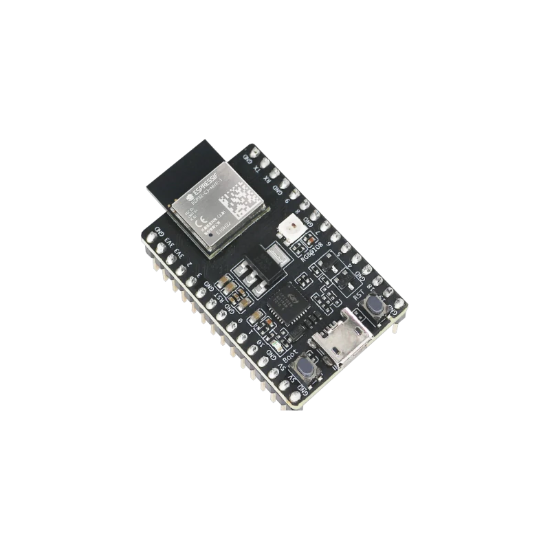
The ESP32-C3-DevKitM-1 carries an ESP32-C3-MINI-1 module with 4 MB of flash in the chip package, a single 32-bit RISC-V core at up to 160 MHz, 400 KB SRAM, 2.4 GHz Wi-Fi and Bluetooth 5 LE (Espressif user guide; ESP32-C3 datasheet v2.4, pp. 3 to 4). It programs over Micro-USB through a CP2102N bridge, and its pins are 3.3 V only (absolute maximum 3.6 V, datasheet p. 54). GPIO2, GPIO8 and GPIO9 are strapping pins, and the addressable RGB LED is on GPIO8.
This is Espressif's own ESP32-C3 board, the one the ESP-IDF examples assume. The ESP32-C3-MINI-1 module (or the -1U with an antenna connector) holds an ESP32-C3 with 4 MB of flash in its package, and every GPIO except the flash bus reaches two 15-pin headers, J1 and J3 (user guide, Header Block).
The ESP32-C3 replaces the classic ESP32's Xtensa cores with one RISC-V core at up to 160 MHz, 400 KB of SRAM and 384 KB of ROM, and keeps 2.4 GHz Wi-Fi (802.11 b/g/n) and Bluetooth 5 LE with long range and mesh, but no Bluetooth Classic (ESP32-C3 datasheet v2.4, pp. 3 to 4). Its ADC1 has 5 channels on GPIO0 to GPIO4; the single ADC2 channel on GPIO5 is not factory-calibrated and does not work on some chip revisions (datasheet p. 49).
Unlike the C3 SuperMini, which uses the chip's own USB, this board has a CP2102N USB-to-UART bridge on UART0 (GPIO20 RX, GPIO21 TX) behind a Micro-USB port, with auto-reset into download mode. The C3's native USB pins, GPIO18 and GPIO19, are on J3 for anyone who wants USB Serial/JTAG on their own connector (user guide).
ESP32-C3-DevKitM-1 pinout
| Pin | Function | Type |
|---|---|---|
| GND | GND | passive |
| 3V3 | 3.3 V3.3 V | power in |
| 3V3 | 3.3 V3.3 V | power in |
| IO2 | GPIO2, ADC1_CH2, FSPIQ, PWM3.3 V only | bidirectional |
| IO3 | GPIO3, ADC1_CH3, PWM3.3 V only | bidirectional |
| GND | GND | passive |
| RST | CHIP_PU, Reset3.3 V | input |
| GND | GND | passive |
| IO0 | GPIO0, ADC1_CH0, XTAL_32K_P, PWM3.3 V only | bidirectional |
| IO1 | GPIO1, ADC1_CH1, XTAL_32K_N, PWM3.3 V only | bidirectional |
| IO10 | GPIO10, FSPICS0, PWM3.3 V only | bidirectional |
| GND | GND | passive |
| 5V | 5 V5 V | power in |
| 5V | 5 V5 V | power in |
| GND | GND | passive |
| GND | GND | passive |
| TX | GPIO21, UART0 TX3.3 V only | bidirectional |
| RX | GPIO20, UART0 RX3.3 V only | bidirectional |
| GND | GND | passive |
| IO9 | GPIO9, BOOT button, I2C SCL (Arduino default)3.3 V only | bidirectional |
| IO8 | GPIO8, RGB LED data, I2C SDA (Arduino default)3.3 V only | bidirectional |
| GND | GND | passive |
| IO7 | GPIO7, FSPID, MTDO, SPI SS (Arduino default), PWM3.3 V only | bidirectional |
| IO6 | GPIO6, FSPICLK, MTCK, SPI MOSI (Arduino default), PWM3.3 V only | bidirectional |
| IO5 | GPIO5, ADC2_CH0, FSPIWP, MTDI, SPI MISO (Arduino default), PWM3.3 V only | bidirectional |
| IO4 | GPIO4, ADC1_CH4, FSPIHD, MTMS, SPI SCK (Arduino default), PWM3.3 V only | bidirectional |
| GND | GND | passive |
| IO18 | GPIO18, USB_D-3.3 V only | bidirectional |
| IO19 | GPIO19, USB_D+3.3 V only | bidirectional |
| GND | GND | passive |
ESP32-C3-DevKitM-1 code
Every example here compiles for its board.
// ESP32-C3-DevKitM-1 on ESP32-C3-DevKitM-1: wiring and a free simulation at https://www.tinkered.ai/components/esp32-c3-devkitm-1
// ESP32-C3-DevKitM-1: a tiny web server that sets the onboard RGB LED (GPIO8).
// The board starts its own Wi-Fi network; join it and open http://192.168.4.1
// Serial Monitor at 115200 on the Micro-USB port.
#include <WiFi.h>
#include <WebServer.h>

#if ESP_ARDUINO_VERSION_MAJOR < 3
#define rgbLedWrite neopixelWrite   // arduino-esp32 2.x names it neopixelWrite
#endif

const char *AP_SSID = "ESP32-C3-LED";
const char *AP_PASS = "c3devkit123";  // at least 8 characters

WebServer server(80);
String colour = "off";

void showColour() {
  if (colour == "red") rgbLedWrite(RGB_BUILTIN, 40, 0, 0);
  else if (colour == "green") rgbLedWrite(RGB_BUILTIN, 0, 40, 0);
  else if (colour == "blue") rgbLedWrite(RGB_BUILTIN, 0, 0, 40);
  else rgbLedWrite(RGB_BUILTIN, 0, 0, 0);
}

void sendPage() {
  String html = "<!doctype html><html><head><meta name=viewport content='width=device-width'>"
                "<title>ESP32-C3 LED</title></head><body style='font-family:sans-serif'>"
                "<h1>ESP32-C3 RGB LED</h1><p>Now: " + colour + "</p><p>"
                "<a href='/set?c=red'>Red</a> | <a href='/set?c=green'>Green</a> | "
                "<a href='/set?c=blue'>Blue</a> | <a href='/set?c=off'>Off</a></p></body></html>";
  server.send(200, "text/html", html);
}

void handleSet() {
  if (server.hasArg("c")) {
    colour = server.arg("c");
    showColour();
    Serial.println("LED: " + colour);
  }
  sendPage();
}

void setup() {
  Serial.begin(115200);
  showColour();
  WiFi.mode(WIFI_AP);
  WiFi.softAP(AP_SSID, AP_PASS);
  Serial.print("Join Wi-Fi ");
  Serial.print(AP_SSID);
  Serial.print(" and open http://");
  Serial.println(WiFi.softAPIP());
  server.on("/", sendPage);
  server.on("/set", handleSet);
  server.begin();
}

void loop() {
  server.handleClient();
}
Before you wire it
- Keep GPIO9 high and GPIO8 high at reset to boot your sketch; GPIO9 low with GPIO8 high enters download mode (datasheet p. 31). Keep GPIO2 high too, as Espressif recommends.
- Use GPIO0 to GPIO4 for analog inputs: they are ADC1, factory-calibrated (datasheet p. 49).
- Keep every pin at 3.3 V or below (datasheet p. 54); level-shift 5 V signals.
- Power the board from one source at a time: Micro-USB, the 5V pins or the 3V3 pins (user guide).
- Use a data-capable Micro-USB cable; charge-only cables power the board but show no port.
- Never rely on analogRead() on GPIO5: ADC2 is not calibrated and is not operable on some chip revisions (datasheet p. 49).
- Never hang a pull-down or a low-at-power-up load on GPIO2, GPIO8 or GPIO9.
- Never drive more than 40 mA from a pin (datasheet p. 55).
- The RGB LED on GPIO8 is an addressable SK68XXMINI-HS; set it with rgbLedWrite(RGB_BUILTIN, r, g, b). Because GPIO8 is also a strapping pin, adding your own load there can stop the board entering download mode.
- The Arduino core's defaults for this generic C3 board put I2C on GPIO8 (SDA) and GPIO9 (SCL); since both are strapping pins and GPIO8 drives the LED, many builds use Wire.begin(4, 5) or other free pins instead.
- GPIO18 and GPIO19 are the C3's native USB Serial/JTAG; wire a USB connector to them for JTAG debugging without an adapter.
- GPIO0 and GPIO1 can take a 32.768 kHz crystal for a more accurate low-power clock.
Specifications
- Chip and core
- ESP32-C3: single-core 32-bit RISC-V, up to 160 MHzEspressif ESP32-C3 datasheet v2.4, p. 3
- Memory
- 400 KB SRAM (16 KB used for cache), 384 KB ROM, 8 KB RTC SRAM; 4 MB flash in the chip package; no PSRAMESP32-C3 datasheet v2.4, p. 4; ESP32-C3-DevKitM-1 user guide, Ordering Information
- Radios
- Wi-Fi 802.11 b/g/n 2.4 GHz and Bluetooth 5 (LE) with Bluetooth mesh; no Bluetooth ClassicESP32-C3 datasheet v2.4, pp. 1, 3
- I/O voltage
- 3.3 V logic; power pins allowed at most 3.6 V. Not 5 V tolerantESP32-C3 datasheet v2.4, p. 54
- GPIO current
- 40 mA source and 28 mA sink typical per pin at maximum drive; 1000 mA cumulative IO output currentESP32-C3 datasheet v2.4, pp. 54 to 55
- Power inputs
- Micro-USB (recommended), the 5V and GND pins, or the 3V3 and GND pins, one at a time. An SGM2212 LDO (800 mA rated) makes 3.3 VESP32-C3-DevKitM-1 user guide, Power Supply Options; schematic V1; SGMICRO SGM2212 product page
- USB
- Micro-USB through a CP2102N USB-to-UART bridge (up to 3 Mbps) on UART0; native USB on GPIO18/GPIO19 at the header onlyESP32-C3-DevKitM-1 user guide; schematic V1
- ADC
- Two 12-bit SAR ADCs: ADC1 on GPIO0 to GPIO4 (factory-calibrated), ADC2 on GPIO5 only (not calibrated, not operable on some revisions)ESP32-C3 datasheet v2.4, pp. 4, 49
- LED and buttons
- Addressable RGB LED (SK68XXMINI-HS) on GPIO8; BOOT button on GPIO9; RESET buttonESP32-C3-DevKitM-1 user guide; schematic V1
From the ESP32-C3-DevKitM-1 user guide, published by Espressif Systems.
Common mistakes
I2C on the default pins upsets the LED and boot
The generic C3 definition puts SDA on GPIO8 and SCL on GPIO9, the RGB LED's line and the BOOT strap. Pull-ups there are fine, but a sensor that holds a line low at reset blocks boot. Prefer Wire.begin(4, 5).
No onboard LED blink with digitalWrite()
The board's only user LED is addressable, so a plain HIGH on GPIO8 does not light it. Use rgbLedWrite() or a library for WS2812-type LEDs.
analogRead() on GPIO5 gives nonsense
GPIO5 is the only ADC2 channel, not calibrated and broken on some revisions (datasheet p. 49). Use GPIO0 to GPIO4 for analog signals.
Missing USB driver
The CP2102N bridge needs Silicon Labs' CP210x driver on older Windows versions. If no COM port appears with a known-good cable, install it.
ESP32-C3-DevKitM-1 questions
What is the difference between the ESP32-C3-DevKitM-1 and the C3 SuperMini?
Both use the ESP32-C3. The DevKitM-1 is Espressif's reference board with the MINI-1 module, a CP2102N USB-to-UART bridge and an RGB LED; the SuperMini is a smaller third-party board that uses the chip's native USB and has a plain LED. The DevKitM-1's bridge keeps Serial and uploads working even when a sketch crashes.
Does the ESP32-C3 support Bluetooth Classic?
No. It has Bluetooth 5 LE, with long range and mesh, but not Classic (datasheet p. 3), so BluetoothSerial does not work. Use a BLE UART service instead.
How do I enter download mode manually?
Hold BOOT (GPIO9), press and release RESET, then release BOOT. With GPIO9 low and GPIO8 high at reset, the chip starts its ROM downloader (datasheet p. 31). The CP2102N auto-reset usually does this for you.
Which ESP32-C3 pins are safe to use?
GPIO0, 1, 3, 4, 5, 6, 7 and 10 are free general I/O on this board; GPIO20 and GPIO21 carry Serial; GPIO18 and 19 are native USB; GPIO2, 8 and 9 are strapping pins that must not be pulled low at reset (user guide, Header Block).
Is the ESP32-C3 5 V tolerant?
No. Its power pins are rated to 3.6 V at most (datasheet p. 54), so a 5 V output into a GPIO can damage it. Use a level shifter or divider.
Build something with the ESP32-C3-DevKitM-1
- Build this
BLE temperature beacon
Broadcast a sensor's reading over Bluetooth LE so a phone app can read it.
- Build this
Wi-Fi status light
Show a web service's status on the onboard RGB LED.
This page as plain Markdown, for ChatGPT, Claude or your own agent. /components/esp32-c3-devkitm-1.md