BNO055
A Bosch 9-axis absolute orientation sensor breakout that fuses accelerometer, gyroscope and magnetometer data on chip and outputs heading, Euler angles and quaternions over I2C.
- Chip supplyVDD 2.4 V to 3.6 V; VDDIO 1.7 V to 3.6 V
- Absolute maximumVDD 4.2 V; VDDIO 3.6 V; logic pins at most VDDIO + 0.3 V
- I2C address0x29 (COM3 high) or 0x28 (COM3 low); Adafruit board defaults to 0x28
- I2CStandard and fast mode up to 400 kHz; uses clock stretching
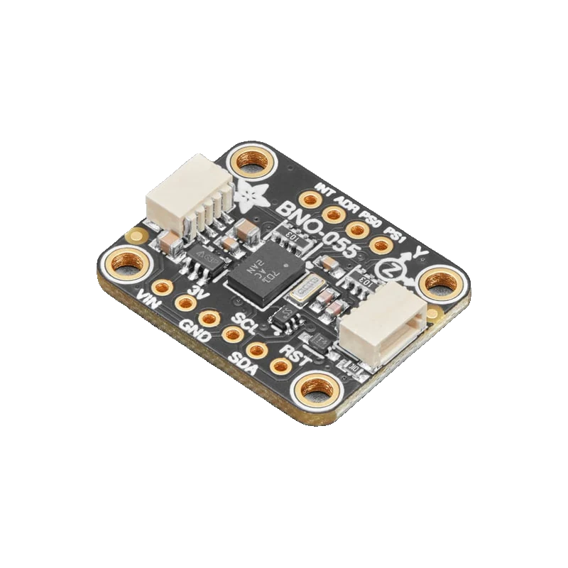
The BNO055 combines an accelerometer, a gyroscope and a magnetometer with a microcontroller running Bosch's fusion software, so it outputs ready-made Euler angles, quaternions, linear acceleration and gravity at 100 Hz (Bosch BNO055 datasheet rev 1.8, pp. 2, 33). It answers at I2C address 0x28 or 0x29 (COM3 low or high) and uses clock stretching (p. 100). The chip runs from 2.4 V to 3.6 V (p. 13); Adafruit's breakout adds a regulator so VIN takes 3.3 V to 5 V, with SDA and SCL safe at 3 V or 5 V logic.
The BNO055 is a system in package: Bosch's accelerometer, gyroscope and magnetometer plus a 32-bit Cortex-M0+ running sensor fusion. Instead of raw axes you read orientation as Euler angles or quaternions, plus linear acceleration with gravity removed, gravity alone and heading, all at 100 Hz in NDOF mode (Bosch datasheet rev 1.8, pp. 2, 33). Ranges run to ±16 g, ±2000 dps and about ±1300 µT on x and y (pp. 2 to 3, 16).
The fusion calibrates itself while you move it: each of system, gyroscope, accelerometer and magnetometer reports a calibration status from 0 to 3, and heading is only trustworthy once the magnetometer reaches 3. Saved offsets can be written back at start-up to skip the dance. The whole package draws at most 12.3 mA with nine axes at 100 Hz (p. 13).
Two practical caveats. The chip runs from 2.4 V to 3.6 V with a 4.2 V absolute maximum (pp. 13, 18), so use a breakout with a regulator such as Adafruit's. And its I2C uses clock stretching (p. 100); Adafruit warns that the BNO055's I2C behaviour does not work well with ESP32 and ESP32-S3 boards and with I2C multiplexers, while RP2040 and others are more reliable (Adafruit guide, pp. 5, 9).
BNO055 pinout
| Pin | Function | Type |
|---|---|---|
| VIN | VIN3.3 V to 5 V | power in |
| 3VO | 3VO3.3 V | power out |
| GND | GND | power in |
| SDA | I2C SDA3 V or 5 V logic, 10 kΩ pull-up | bidirectional |
| SCL | I2C SCL3 V or 5 V logic, 10 kΩ pull-up | input |
| RST | Reset (active low)5 V safe | input |
| INT | Interrupt3 V | output |
| ADR | I2C address select | input |
| PS0 | Protocol select | input |
How to wire the BNO055
Pin by pin, for the board you have.
| BNO055 | Arduino Uno | Note |
|---|---|---|
| VIN | 5V | |
| GND | GND | |
| SCL | A5 | |
| SDA | A4 |
| BNO055 | ESP32 DevKit V1 | Note |
|---|---|---|
| VIN | 3V3 | |
| GND | GND | |
| SCL | GPIO22 (D22) | |
| SDA | GPIO21 (D21) |
- Adafruit reports that the BNO055's I2C (it stretches the clock) does not work well with ESP32 boards (guide, pp. 5, 9). Expect occasional bus errors; if they persist, use another board for this sensor or its UART mode (PS1 high).
| BNO055 | Raspberry Pi Pico | Note |
|---|---|---|
| VIN | 3V3(OUT) | |
| GND | GND | |
| SCL | GP5 | |
| SDA | GP4 |
BNO055 code
Every example here compiles for its board.
// BNO055 on Arduino Uno: wiring and a free simulation at https://www.tinkered.ai/components/bno055
// BNO055 on an Arduino Uno: VIN 5V, SDA A4, SCL A5, address 0x28
#include <Wire.h>
#include <Adafruit_Sensor.h>
#include <Adafruit_BNO055.h>

Adafruit_BNO055 bno(55, 0x28, &Wire);

void setup() {
  Serial.begin(115200);
  Wire.begin();
  if (!bno.begin()) {  // starts in NDOF fusion mode
    Serial.println("BNO055 not found at 0x28. Check wiring and ADR.");
    while (true) delay(10);
  }
  delay(1000);
  bno.setExtCrystalUse(true);  // use the breakout's external crystal, as in Adafruit's examples
  Serial.println("BNO055 ready. Move it in a figure eight to calibrate the magnetometer.");
}

void loop() {
  sensors_event_t event;
  bno.getEvent(&event);  // Euler angles in degrees
  uint8_t sys, gyro, accel, mag;
  bno.getCalibration(&sys, &gyro, &accel, &mag);
  Serial.print("Heading: ");
  Serial.print(event.orientation.x, 1);
  Serial.print("  Roll: ");
  Serial.print(event.orientation.y, 1);
  Serial.print("  Pitch: ");
  Serial.print(event.orientation.z, 1);
  Serial.print("   Calibration sys/gyro/accel/mag: ");
  Serial.print(sys); Serial.print("/");
  Serial.print(gyro); Serial.print("/");
  Serial.print(accel); Serial.print("/");
  Serial.println(mag);
  delay(100);  // fusion data updates at 100 Hz
}
// BNO055 on ESP32 DevKit V1: wiring and a free simulation at https://www.tinkered.ai/components/bno055
// BNO055 on an ESP32 DevKit V1: VIN 3V3, SDA GPIO21, SCL GPIO22, address 0x28
#include <Wire.h>
#include <Adafruit_Sensor.h>
#include <Adafruit_BNO055.h>

Adafruit_BNO055 bno(55, 0x28, &Wire);

void setup() {
  Serial.begin(115200);
  Wire.begin(21, 22);  // SDA, SCL
  if (!bno.begin()) {  // starts in NDOF fusion mode
    Serial.println("BNO055 not found at 0x28. Check wiring and ADR.");
    while (true) delay(10);
  }
  delay(1000);
  bno.setExtCrystalUse(true);  // use the breakout's external crystal, as in Adafruit's examples
  Serial.println("BNO055 ready. Move it in a figure eight to calibrate the magnetometer.");
}

void loop() {
  sensors_event_t event;
  bno.getEvent(&event);  // Euler angles in degrees
  uint8_t sys, gyro, accel, mag;
  bno.getCalibration(&sys, &gyro, &accel, &mag);
  Serial.print("Heading: ");
  Serial.print(event.orientation.x, 1);
  Serial.print("  Roll: ");
  Serial.print(event.orientation.y, 1);
  Serial.print("  Pitch: ");
  Serial.print(event.orientation.z, 1);
  Serial.print("   Calibration sys/gyro/accel/mag: ");
  Serial.print(sys); Serial.print("/");
  Serial.print(gyro); Serial.print("/");
  Serial.print(accel); Serial.print("/");
  Serial.println(mag);
  delay(100);  // fusion data updates at 100 Hz
}
// BNO055 on Raspberry Pi Pico: wiring and a free simulation at https://www.tinkered.ai/components/bno055
// BNO055 on a Raspberry Pi Pico (arduino-pico): VIN 3V3(OUT), SDA GP4, SCL GP5, address 0x28
#include <Wire.h>
#include <Adafruit_Sensor.h>
#include <Adafruit_BNO055.h>

Adafruit_BNO055 bno(55, 0x28, &Wire);

void setup() {
  Serial.begin(115200);
  Wire.setSDA(4);
  Wire.setSCL(5);
  Wire.begin();
  if (!bno.begin()) {  // starts in NDOF fusion mode
    Serial.println("BNO055 not found at 0x28. Check wiring and ADR.");
    while (true) delay(10);
  }
  delay(1000);
  bno.setExtCrystalUse(true);  // use the breakout's external crystal, as in Adafruit's examples
  Serial.println("BNO055 ready. Move it in a figure eight to calibrate the magnetometer.");
}

void loop() {
  sensors_event_t event;
  bno.getEvent(&event);  // Euler angles in degrees
  uint8_t sys, gyro, accel, mag;
  bno.getCalibration(&sys, &gyro, &accel, &mag);
  Serial.print("Heading: ");
  Serial.print(event.orientation.x, 1);
  Serial.print("  Roll: ");
  Serial.print(event.orientation.y, 1);
  Serial.print("  Pitch: ");
  Serial.print(event.orientation.z, 1);
  Serial.print("   Calibration sys/gyro/accel/mag: ");
  Serial.print(sys); Serial.print("/");
  Serial.print(gyro); Serial.print("/");
  Serial.print(accel); Serial.print("/");
  Serial.println(mag);
  delay(100);  // fusion data updates at 100 Hz
}
Before you wire it
- Wait for the magnetometer calibration status to reach 3 before trusting heading; move the board in a figure eight.
- Save calibration offsets once calibrated and restore them at start-up with setSensorOffsets().
- Keep I2C at 400 kHz or less and allow clock stretching (datasheet, p. 100).
- Mount it away from motors, speakers and steel screws that disturb the magnetometer.
- Never power a bare BNO055 above 3.6 V (p. 13); use a regulated breakout on 5 V boards.
- Never put it behind an I2C multiplexer without testing; Adafruit reports problems (guide, p. 5).
- Never rely on the ESP32's I2C with it for safety-critical motion without long testing (guide, p. 9).
- Fusion mode NDOF uses all three sensors; IMU mode drops the magnetometer for relative orientation without magnetic disturbance (datasheet, p. 33).
- Euler angles hit gimbal lock near ±90° pitch; use quaternions for full 3D rotation.
- The Adafruit board's ADR pin moves the address to 0x29 so two sensors share a bus.
- UART mode (PS1 high) avoids I2C clock stretching entirely on boards that handle it poorly.
Specifications
- Chip supply
- VDD 2.4 V to 3.6 V; VDDIO 1.7 V to 3.6 VBosch BNO055 datasheet rev 1.8, p. 13
- Absolute maximum
- VDD 4.2 V; VDDIO 3.6 V; logic pins at most VDDIO + 0.3 VBosch BNO055 datasheet rev 1.8, p. 18
- I2C address
- 0x29 (COM3 high) or 0x28 (COM3 low); Adafruit board defaults to 0x28Bosch BNO055 datasheet rev 1.8, p. 100; Adafruit BNO055 guide (PDF), p. 10
- I2C
- Standard and fast mode up to 400 kHz; uses clock stretchingBosch BNO055 datasheet rev 1.8, p. 100
- Fusion output
- Quaternion, Euler angles, rotation vector, linear acceleration, gravity, heading at 100 Hz (NDOF)Bosch BNO055 datasheet rev 1.8, pp. 2, 33
- Sensor ranges
- Accelerometer ±2 to ±16 g; gyroscope up to ±2000 dps; magnetometer ±1300 µT (x, y), ±2500 µT (z)Bosch BNO055 datasheet rev 1.8, pp. 2 to 3, 16
- Current
- 12.3 mA max (9 DOF at 100 Hz); 0.04 mA suspendBosch BNO055 datasheet rev 1.8, p. 13
- Breakout
- VIN 3.3 V to 5 V; 3VO about 50 mA; SDA and SCL 3 V or 5 V logic with 10 kΩ pull-ups; RST 5 V safe; INT 3 VAdafruit BNO055 guide (PDF), pp. 9 to 10
- Microcontroller compatibility
- Adafruit reports poor I2C operation with ESP32, ESP32-S3 and I2C multiplexers; RP2040 more reliableAdafruit BNO055 guide (PDF), pp. 5, 9
From the BNO055 product page and datasheet, published by Bosch Sensortec.
Common mistakes
Heading drifts or jumps
The magnetometer is uncalibrated (status below 3) or there is iron nearby. Calibrate in a figure eight away from metal and check getCalibration().
Random I2C errors on an ESP32
The BNO055 stretches the clock and Adafruit reports it does not work well with ESP32 boards (guide, pp. 5, 9). Try a shorter cable and 100 kHz, use UART mode, or move the sensor to an RP2040 or AVR board.
Wrong address
The chip defaults to 0x29 with COM3 high (datasheet, p. 100) but Adafruit's board holds ADR low for 0x28. Scan the bus and match the constructor.
Expecting zero at start
Heading is absolute, relative to magnetic north once calibrated, not zero at power-up. Subtract the starting heading if you need relative turns.
BNO055 questions
What is the BNO055's I2C address?
0x28 with COM3 (ADR) low and 0x29 with it high (Bosch datasheet rev 1.8, p. 100). The Adafruit breakout defaults to 0x28.
Does the BNO055 work with an ESP32?
Often, but not reliably: its I2C uses clock stretching (p. 100), and Adafruit reports it does not work well with ESP32 and ESP32-S3 (guide, pp. 5, 9). For robust projects use UART mode or a board like the RP2040.
BNO055 or MPU6050?
The MPU6050 gives raw accelerometer and gyro data, so your code does the fusion and it has no magnetometer for absolute heading. The BNO055 outputs fused absolute orientation directly.
How do I calibrate the BNO055?
Leave it still for the gyro, place it in several orientations for the accelerometer, and move it in a figure eight for the magnetometer, until getCalibration() reports 3 for each. Save the offsets to EEPROM.
Is the BNO055 5 V tolerant?
The chip is not: VDD is 2.4 V to 3.6 V (p. 13). Adafruit's breakout has a regulator and accepts 3 V or 5 V logic on SDA and SCL (guide, pp. 9 to 10).
Build something with the BNO055
- Build this
Digital compass
Show calibrated heading in degrees.
- Build this
3D orientation viewer
Stream quaternions to a PC to rotate a 3D model.
- Build this
Camera gimbal
Hold a small camera level with two servos.
This page as plain Markdown, for ChatGPT, Claude or your own agent. /components/bno055.md