ICM-20948
A TDK InvenSense 9-axis IMU breakout (accelerometer, gyroscope and AK09916 magnetometer) read over I2C or SPI, for orientation, heading and motion tracking.
- SupplyVDD 1.71 V to 3.6 V; VDDIO 1.71 V to 1.95 V
- Absolute maximumVDD -0.5 V to 4 V; VDDIO -0.3 V to 2.5 V
- Gyroscope±250, ±500, ±1000, ±2000 dps; 16-bit; 131 LSB/dps at ±250 dps
- Accelerometer±2, ±4, ±8, ±16 g; 16-bit
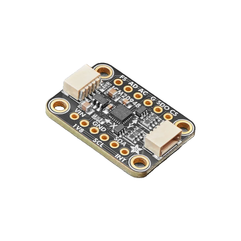
The ICM-20948 is TDK InvenSense's 9-axis motion sensor: a 3-axis gyroscope (±250 to ±2000 dps), a 3-axis accelerometer (±2 to ±16 g) and an AK09916 magnetometer (±4900 µT), with 16-bit outputs and 3.11 mA in 9-axis mode (ICM-20948 datasheet rev 1.3, pp. 9 to 13). It talks I2C at 400 kHz at address 0x68 or 0x69, or SPI at 7 MHz (pp. 9, 28). The chip's I/O runs at only 1.71 V to 1.95 V (p. 9), so use a breakout with level shifting, such as Adafruit's (VIN 3 V to 5 V, default address 0x69).
The ICM-20948 is the successor to the MPU-9250: one package with a 3-axis gyroscope, a 3-axis accelerometer and an Asahi Kasei AK09916 magnetometer, plus a Digital Motion Processor (DMP) that can run sensor fusion on chip (TDK datasheet rev 1.3, p. 9). Gyro full scale is ±250, ±500, ±1000 or ±2000 dps and accelerometer full scale ±2, ±4, ±8 or ±16 g, all on 16-bit ADCs; the magnetometer covers ±4900 µT at 0.15 µT per LSB (pp. 10, 13).
Its supplies are the catch for hobby use: VDD is 1.71 V to 3.6 V, but VDDIO, which sets the I2C and SPI levels, is 1.71 V to 1.95 V with a 2.5 V absolute maximum (pp. 9, 18). A 3.3 V microcontroller wired straight to a bare chip exceeds that. Adafruit's breakout has a 1.8 V regulator and level shifting with 10 kΩ pull-ups, so it takes 3 V to 5 V on VIN and logic (Adafruit guide, pp. 5 to 7).
Running all nine axes with the DMP off draws 3.11 mA; full-chip sleep drops to 8 µA (datasheet, p. 13). The address is 0x69 with AD0 high (Adafruit's default) and 0x68 with AD0 low (pp. 14, 28), so two boards can share a bus.
ICM-20948 pinout
| Pin | Function | Type |
|---|---|---|
| VIN | VIN3 V to 5 V, equal to your board's logic level | power in |
| 1V8 | 1V81.8 V | power out |
| GND | GND | power in |
| SCL | I2C SCL, SPI SCKLevel shifted, 10 kΩ pull-up | input |
| SDA | I2C SDA, SPI MOSILevel shifted, 10 kΩ pull-up | bidirectional |
| SDO | SPI MISO, I2C address select | bidirectional |
| CS | SPI CS | input |
| INT | Interrupt | output |
| FS | Frame sync | input |
| AUX | Auxiliary I2C clock and data | bidirectional |
How to wire the ICM-20948
Pin by pin, for the board you have.
| ICM-20948 | Arduino Uno | Note |
|---|---|---|
| VIN | 5V | |
| GND | GND | |
| SCL | A5 | |
| SDA | A4 |
- Only use a breakout with level shifting (Adafruit, SparkFun): the bare chip's I/O limit is 2.5 V absolute maximum (datasheet, p. 18).
| ICM-20948 | ESP32 DevKit V1 | Note |
|---|---|---|
| VIN | 3V3 | |
| GND | GND | |
| SCL | GPIO22 (D22) | |
| SDA | GPIO21 (D21) |
- Power VIN from 3V3 so the level-shifted bus sits at 3.3 V.
| ICM-20948 | Raspberry Pi Pico | Note |
|---|---|---|
| VIN | 3V3(OUT) | |
| GND | GND | |
| SCL | GP5 | |
| SDA | GP4 |
- Power VIN from 3V3(OUT), not VBUS.
ICM-20948 code
Every example here compiles for its board.
// ICM-20948 on Arduino Uno: wiring and a free simulation at https://www.tinkered.ai/components/icm-20948
// ICM-20948 on an Arduino Uno: VIN 5V, SDA A4, SCL A5, address 0x69
#include <Wire.h>
#include <Adafruit_Sensor.h>
#include <Adafruit_ICM20948.h>

Adafruit_ICM20948 icm;

void setup() {
  Serial.begin(115200);
  Wire.begin();
  if (!icm.begin_I2C(0x69, &Wire)) {
    Serial.println("ICM-20948 not found at 0x69. Check wiring and the ADR jumper.");
    while (true) delay(10);
  }
  icm.setAccelRange(ICM20948_ACCEL_RANGE_4_G);
  icm.setGyroRange(ICM20948_GYRO_RANGE_500_DPS);
  Serial.println("ICM-20948 ready");
}

void loop() {
  sensors_event_t accel, gyro, temp, mag;
  icm.getEvent(&accel, &gyro, &temp, &mag);
  Serial.print("Accel m/s^2: ");
  Serial.print(accel.acceleration.x, 2); Serial.print(", ");
  Serial.print(accel.acceleration.y, 2); Serial.print(", ");
  Serial.print(accel.acceleration.z, 2);
  Serial.print("   Gyro rad/s: ");
  Serial.print(gyro.gyro.x, 2); Serial.print(", ");
  Serial.print(gyro.gyro.y, 2); Serial.print(", ");
  Serial.print(gyro.gyro.z, 2);
  Serial.print("   Mag uT: ");
  Serial.print(mag.magnetic.x, 1); Serial.print(", ");
  Serial.print(mag.magnetic.y, 1); Serial.print(", ");
  Serial.println(mag.magnetic.z, 1);
  delay(200);
}
// ICM-20948 on ESP32 DevKit V1: wiring and a free simulation at https://www.tinkered.ai/components/icm-20948
// ICM-20948 on an ESP32 DevKit V1: VIN 3V3, SDA GPIO21, SCL GPIO22, address 0x69
#include <Wire.h>
#include <Adafruit_Sensor.h>
#include <Adafruit_ICM20948.h>

Adafruit_ICM20948 icm;

void setup() {
  Serial.begin(115200);
  Wire.begin(21, 22);  // SDA, SCL
  if (!icm.begin_I2C(0x69, &Wire)) {
    Serial.println("ICM-20948 not found at 0x69. Check wiring and the ADR jumper.");
    while (true) delay(10);
  }
  icm.setAccelRange(ICM20948_ACCEL_RANGE_4_G);
  icm.setGyroRange(ICM20948_GYRO_RANGE_500_DPS);
  Serial.println("ICM-20948 ready");
}

void loop() {
  sensors_event_t accel, gyro, temp, mag;
  icm.getEvent(&accel, &gyro, &temp, &mag);
  Serial.print("Accel m/s^2: ");
  Serial.print(accel.acceleration.x, 2); Serial.print(", ");
  Serial.print(accel.acceleration.y, 2); Serial.print(", ");
  Serial.print(accel.acceleration.z, 2);
  Serial.print("   Gyro rad/s: ");
  Serial.print(gyro.gyro.x, 2); Serial.print(", ");
  Serial.print(gyro.gyro.y, 2); Serial.print(", ");
  Serial.print(gyro.gyro.z, 2);
  Serial.print("   Mag uT: ");
  Serial.print(mag.magnetic.x, 1); Serial.print(", ");
  Serial.print(mag.magnetic.y, 1); Serial.print(", ");
  Serial.println(mag.magnetic.z, 1);
  delay(200);
}
// ICM-20948 on Raspberry Pi Pico: wiring and a free simulation at https://www.tinkered.ai/components/icm-20948
// ICM-20948 on a Raspberry Pi Pico (arduino-pico): VIN 3V3(OUT), SDA GP4, SCL GP5, address 0x69
#include <Wire.h>
#include <Adafruit_Sensor.h>
#include <Adafruit_ICM20948.h>

Adafruit_ICM20948 icm;

void setup() {
  Serial.begin(115200);
  Wire.setSDA(4);
  Wire.setSCL(5);
  Wire.begin();
  if (!icm.begin_I2C(0x69, &Wire)) {
    Serial.println("ICM-20948 not found at 0x69. Check wiring and the ADR jumper.");
    while (true) delay(10);
  }
  icm.setAccelRange(ICM20948_ACCEL_RANGE_4_G);
  icm.setGyroRange(ICM20948_GYRO_RANGE_500_DPS);
  Serial.println("ICM-20948 ready");
}

void loop() {
  sensors_event_t accel, gyro, temp, mag;
  icm.getEvent(&accel, &gyro, &temp, &mag);
  Serial.print("Accel m/s^2: ");
  Serial.print(accel.acceleration.x, 2); Serial.print(", ");
  Serial.print(accel.acceleration.y, 2); Serial.print(", ");
  Serial.print(accel.acceleration.z, 2);
  Serial.print("   Gyro rad/s: ");
  Serial.print(gyro.gyro.x, 2); Serial.print(", ");
  Serial.print(gyro.gyro.y, 2); Serial.print(", ");
  Serial.print(gyro.gyro.z, 2);
  Serial.print("   Mag uT: ");
  Serial.print(mag.magnetic.x, 1); Serial.print(", ");
  Serial.print(mag.magnetic.y, 1); Serial.print(", ");
  Serial.println(mag.magnetic.z, 1);
  delay(200);
}
Before you wire it
- Use a level-shifted breakout with any 3.3 V or 5 V board: VDDIO is 1.71 V to 1.95 V (datasheet, p. 9).
- Calibrate the magnetometer (rotate through all orientations and record min and max per axis) before computing heading.
- Keep the board away from motors, speakers and steel; they distort the ±4900 µT magnetometer's field.
- Choose the address deliberately: 0x69 by default on Adafruit's board, 0x68 with the ADR jumper bridged (guide, p. 7).
- Never connect a bare ICM-20948 module's I/O to 3.3 V logic without checking its level shifting; 2.5 V is the absolute maximum (p. 18).
- Never expect a stable heading from the gyroscope alone: integrate it with the accelerometer and magnetometer (sensor fusion).
- Never put it at 0x68 alongside a DS3231 RTC or an MPU6050, which also use 0x68.
- The magnetometer is reached through the chip's internal auxiliary I2C master; the library sets it up, so it does not appear as a separate address on your bus.
- Fusion algorithms such as Madgwick or Mahony turn the nine axes into roll, pitch and heading on the microcontroller; the on-chip DMP can do it with TDK's firmware.
- Gyro sensitivity at ±250 dps is 131 LSB per dps (p. 11); wider ranges trade resolution for headroom.
- Full-chip sleep at 8 µA (p. 13) suits wake-on-motion designs.
Specifications
- Supply
- VDD 1.71 V to 3.6 V; VDDIO 1.71 V to 1.95 VTDK InvenSense ICM-20948 datasheet DS-000189 rev 1.3, pp. 1, 9
- Absolute maximum
- VDD -0.5 V to 4 V; VDDIO -0.3 V to 2.5 VTDK InvenSense ICM-20948 datasheet DS-000189 rev 1.3, p. 18
- Gyroscope
- ±250, ±500, ±1000, ±2000 dps; 16-bit; 131 LSB/dps at ±250 dpsTDK InvenSense ICM-20948 datasheet DS-000189 rev 1.3, pp. 10 to 11
- Accelerometer
- ±2, ±4, ±8, ±16 g; 16-bitTDK InvenSense ICM-20948 datasheet DS-000189 rev 1.3, p. 10
- Magnetometer
- AK09916, ±4900 µT, 0.15 µT/LSBTDK InvenSense ICM-20948 datasheet DS-000189 rev 1.3, pp. 9 to 10, 13
- Interfaces
- I2C fast mode 400 kHz; SPI 7 MHzTDK InvenSense ICM-20948 datasheet DS-000189 rev 1.3, pp. 1, 9
- I2C address
- 0x68 (AD0 low) or 0x69 (AD0 high); WHO_AM_I 0xEATDK InvenSense ICM-20948 datasheet DS-000189 rev 1.3, pp. 28, 36
- Current
- 3.11 mA 9-axis (DMP off); 8 µA full-chip sleepTDK InvenSense ICM-20948 datasheet DS-000189 rev 1.3, p. 13
- Breakout
- 1.8 V regulator and level shifting; VIN 3 V to 5 V; 10 kΩ pull-ups; 0x69 default, ADR jumper for 0x68Adafruit ICM-20948 guide (PDF), pp. 5 to 7
From the ICM-20948 product page and datasheet, published by TDK InvenSense.
Common mistakes
Scanning finds 0x68, code looks at 0x69
Some boards (and the Adafruit board with its ADR jumper bridged) sit at 0x68 (datasheet, p. 28). Pass the right address to begin_I2C().
Heading swings when the board tilts
A raw magnetometer heading only works flat. Use tilt compensation from the accelerometer, or a fusion filter.
Magnetometer reads the same offset everywhere
Hard-iron offsets from nearby steel and the PCB itself dominate until calibrated. Subtract the centre of the min/max range on each axis.
Treating it as an MPU-9250
Register maps differ: the ICM-20948 uses register banks and a different magnetometer (AK09916). Use an ICM-20948 library.
ICM-20948 questions
What is the ICM-20948's I2C address?
0x68 with AD0 low or 0x69 with AD0 high (TDK datasheet rev 1.3, p. 28). Adafruit's and SparkFun's boards default to 0x69; WHO_AM_I reads 0xEA (p. 36).
Is the ICM-20948 3.3 V compatible?
VDD runs to 3.6 V, but the I/O supply VDDIO is 1.71 V to 1.95 V (p. 9). Breakouts from Adafruit and SparkFun add the level shifting that makes it safe at 3.3 V and 5 V.
ICM-20948 or MPU-9250?
The ICM-20948 is TDK's newer 9-axis part with lower power (3.11 mA for nine axes, p. 13) and a newer magnetometer; TDK has discontinued the MPU-9250, so new designs should use the ICM-20948.
ICM-20948 or BNO055?
The BNO055 outputs fused orientation directly. The ICM-20948 gives raw nine-axis data (or DMP output with TDK firmware), so you choose and tune the fusion filter yourself.
Why is the gyro reading not zero at rest?
Every gyroscope has a zero-rate offset. Average a few hundred samples at rest at start-up and subtract them.
Build something with the ICM-20948
- Build this
Tilt-compensated compass
Show heading that stays correct when the board tilts.
- Build this
Head tracker
Stream yaw, pitch and roll to a PC for a flight simulator.
- Build this
Motion logger
Record nine-axis data from a skateboard or a drone.
This page as plain Markdown, for ChatGPT, Claude or your own agent. /components/icm-20948.md