GY-271 Compass (QMC5883L)
A 3-axis magnetometer compass module on QST's QMC5883L, ±8 gauss range and 1° to 2° heading accuracy over I2C.
- Field range±2 G or ±8 G, selectable
- Sensitivity12000 LSB/G at ±2 G; 3000 LSB/G at ±8 G
- Field resolution2 mG (16-bit ADC)
- Heading accuracy1° to 2°
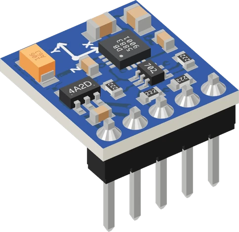
The GY-271 is a 3-axis magnetometer module that today carries QST's QMC5883L: ±2 or ±8 gauss range, a 16-bit ADC with 2 milligauss resolution, and 1° to 2° compass heading accuracy, at I2C address 0x0D (QST QMC5883L datasheet Rev A, pp. 2, 4, 13). Wire VCC to your board's logic voltage (the module regulates it to 3.3 V), GND to GND, and SDA and SCL to the I2C pins. Older GY-271 boards carry Honeywell's HMC5883L at 0x1E, which needs a different library (Honeywell HMC5883L datasheet, p. 11).
The GY-271 is a small blue breakout for a 3-axis magnetic sensor, sold as a digital compass. Current boards carry the QMC5883L from QST, a magneto-resistive sensor based on AMR technology licensed from Honeywell, with a 16-bit ADC, offset cancellation and temperature compensation (QST datasheet Rev A, p. 2). It measures the magnetic field on three axes, and a compass heading comes from the X and Y readings with the board held level.
The chip runs from 2.16 V to 3.6 V (p. 4). The GY-271 module adds a 3.3 V regulator, a MOSFET level shifter on SDA and SCL with 2.2 kΩ pull-ups to the module's VCC, and a 1x5 header: VCC, GND, SCL, SDA and DRDY. DRDY goes high when a new measurement is ready to read (p. 6) and is optional. Feed VCC from the board's logic voltage so the I2C lines idle at the level the microcontroller expects.
Two chips share the GY-271 name, and they are not interchangeable in software. The QMC5883L answers at 0x0D (QST datasheet, p. 13); the older Honeywell HMC5883L answered at 0x1E (Honeywell datasheet, p. 11), with a different register map. An I2C scan settles which one a board carries. The QMC5883L offers ±2 G (12000 LSB/G) or ±8 G (3000 LSB/G) ranges at 10, 50, 100 or 200 Hz (p. 4).
GY-271 Compass (QMC5883L) pinout
| Pin | Function | Type |
|---|---|---|
| DRDY | Digital | output |
| SDA | I2C SDA | bidirectional |
| SCL | I2C SCL | bidirectional |
| GND | GND | power in |
| VCC | VCC: 3-5 V (into the board's 3.3 V regulator)3–5 V | power in |
How to wire the GY-271 Compass (QMC5883L)
Pin by pin, for the board you have.
| GY-271 Compass (QMC5883L) | Arduino Uno | Note |
|---|---|---|
| VCC | 5V | |
| GND | GND | |
| SDA | SDA | |
| SCL | SCL |
| GY-271 Compass (QMC5883L) | ESP32 DevKit V1 | Note |
|---|---|---|
| VCC | 3V3 | |
| GND | GND | |
| SDA | GPIO21 (D21) | |
| SCL | GPIO22 (D22) |
| GY-271 Compass (QMC5883L) | Raspberry Pi Pico | Note |
|---|---|---|
| VCC | 3V3 | |
| GND | GND | |
| SDA | GP4 | |
| SCL | GP5 |
GY-271 Compass (QMC5883L) code
Every example here compiles for its board.
// GY-271 Compass (QMC5883L) on Arduino Uno: wiring and a free simulation at https://www.tinkered.ai/components/gy-271
// lib_deps = mprograms/QMC5883LCompass
#include <QMC5883LCompass.h>

QMC5883LCompass compass;

const char* const POINTS[16] = {"N", "NNE", "NE", "ENE", "E", "ESE", "SE", "SSE", "S", "SSW", "SW", "WSW", "W", "WNW", "NW", "NNW"};

void setup() {
  Serial.begin(9600);
  compass.init();            // Wire.begin(), then continuous 200 Hz, ±8 G
  Serial.println("Compass ready");
}

void loop() {
  compass.read();
  int x = compass.getX();
  int y = compass.getY();
  int z = compass.getZ();

  int heading = compass.getAzimuth();   // -180..179
  if (heading < 0) heading += 360;      // 0..359, clockwise from magnetic north

  // the 16-point name: 22.5° each, N centred on 0
  const char* point = POINTS[(int)((heading + 11.25) / 22.5) % 16];

  Serial.print("heading ");
  Serial.print(heading);
  Serial.print(" ");
  Serial.print(point);
  Serial.print("  x ");
  Serial.print(x);
  Serial.print(" y ");
  Serial.print(y);
  Serial.print(" z ");
  Serial.println(z);
  delay(250);
}
// GY-271 Compass (QMC5883L) on ESP32 DevKit V1: wiring and a free simulation at https://www.tinkered.ai/components/gy-271
// lib_deps = mprograms/QMC5883LCompass
#include <QMC5883LCompass.h>

QMC5883LCompass compass;

const char* const POINTS[16] = {"N", "NNE", "NE", "ENE", "E", "ESE", "SE", "SSE", "S", "SSW", "SW", "WSW", "W", "WNW", "NW", "NNW"};

void setup() {
  Serial.begin(9600);
  compass.init();            // Wire.begin(), then continuous 200 Hz, ±8 G
  Serial.println("Compass ready");
}

void loop() {
  compass.read();
  int x = compass.getX();
  int y = compass.getY();
  int z = compass.getZ();

  int heading = compass.getAzimuth();   // -180..179
  if (heading < 0) heading += 360;      // 0..359, clockwise from magnetic north

  // the 16-point name: 22.5° each, N centred on 0
  const char* point = POINTS[(int)((heading + 11.25) / 22.5) % 16];

  Serial.print("heading ");
  Serial.print(heading);
  Serial.print(" ");
  Serial.print(point);
  Serial.print("  x ");
  Serial.print(x);
  Serial.print(" y ");
  Serial.print(y);
  Serial.print(" z ");
  Serial.println(z);
  delay(250);
}
// GY-271 Compass (QMC5883L) on Raspberry Pi Pico: wiring and a free simulation at https://www.tinkered.ai/components/gy-271
// lib_deps = mprograms/QMC5883LCompass
#include <QMC5883LCompass.h>

QMC5883LCompass compass;

const char* const POINTS[16] = {"N", "NNE", "NE", "ENE", "E", "ESE", "SE", "SSE", "S", "SSW", "SW", "WSW", "W", "WNW", "NW", "NNW"};

void setup() {
  Serial.begin(9600);
  compass.init();            // Wire.begin(), then continuous 200 Hz, ±8 G
  Serial.println("Compass ready");
}

void loop() {
  compass.read();
  int x = compass.getX();
  int y = compass.getY();
  int z = compass.getZ();

  int heading = compass.getAzimuth();   // -180..179
  if (heading < 0) heading += 360;      // 0..359, clockwise from magnetic north

  // the 16-point name: 22.5° each, N centred on 0
  const char* point = POINTS[(int)((heading + 11.25) / 22.5) % 16];

  Serial.print("heading ");
  Serial.print(heading);
  Serial.print(" ");
  Serial.print(point);
  Serial.print("  x ");
  Serial.print(x);
  Serial.print(" y ");
  Serial.print(y);
  Serial.print(" z ");
  Serial.println(z);
  delay(250);
}
Before you wire it
- VCC to the board's logic supply: 3V3 on an ESP32, ESP8266, Pico or STM32 (on 5V the module's pull-ups put 5 V on their I2C pins); 5V or 3V3 on an Uno, Nano, Mega or UNO R4. GND to GND. SDA and SCL to the board's I2C pins: A4/A5 on an Uno or Nano, 20/21 on a Mega, IO21/IO22 on an ESP32, D2/D1 on an ESP8266, GP4/GP5 on a Pico.
- Use mprograms' QMC5883LCompass library (#include <QMC5883LCompass.h>, lib_deps = mprograms/QMC5883LCompass): compass.init() in setup(), then compass.read() and compass.getAzimuth() (or getX()/getY()/getZ()) in loop().
- getAzimuth() returns -180 to 179. For a 0-359 heading add 360 to a negative one.
- Keep the board flat and level for a heading: tilted, the plain heading is off by tens of degrees. For a tilted compass, combine it with an accelerometer (MPU-6050) and tilt-compensate.
- compass.init() calls Wire.begin() itself.
- On an ESP32, a Pico or an STM32 with other pins, set them before init(): Wire.begin(sda, scl) on an ESP32, Wire.setSDA()/Wire.setSCL() on a Pico or STM32.
- On an ESP8266, init() puts I2C back on D2 (SDA) and D1 (SCL): wire the module there.
- Raw register code (without the library): write 0x0B = 0x01, then 0x09 = 0x1D (continuous, 200 Hz, ±8 G, OSR 512). Read all six bytes from 0x00 in one go, X, Y, Z low byte first. Reading 0x00-0x04 locks the data registers until 0x05 is read: a sketch that reads only X and Y never sees a new measurement.
- No Adafruit_HMC5883_Unified or other HMC5883L libraries on this board: they look at 0x1E, where nothing answers.
- No 5 V on VCC with a 3.3 V board (ESP32, ESP8266, Pico, STM32 except its 5 V tolerant pins).
- No extra pull-ups on SDA/SCL: the module has 2.2 kΩ ones.
- Do not promise true north: the chip gives magnetic north. Add the place's declination (setMagneticDeclination(degrees, minutes)) for true north.
- Do not place it next to a motor, a speaker, a relay or a magnet and expect a heading.
- Wire VCC to the microcontroller board's logic supply: 3V3 on an ESP32, ESP8266, Pico or STM32, 5V or 3V3 on an Uno. The module's 3.3 V regulator feeds the chip, whose own range is 2.16 V to 3.6 V (QST datasheet, p. 4), and its 2.2 kΩ pull-ups take SDA and SCL to VCC.
- No extra pull-ups are needed: the module already has them.
- DRDY is optional. It goes high when a new sample is ready and drops once the data is read (QST datasheet, pp. 6, 15); wire it to an interrupt pin only if you want to avoid polling.
- Keep the module several centimetres from motors, speakers, relays, magnets and steel screws. The Earth's field is weak, and nearby iron or currents swamp it.
- Mount the board flat and level for a plain heading. Tilt it and the heading drifts by tens of degrees; combine it with an accelerometer to tilt-compensate.
Specifications
- Field range
- ±2 G or ±8 G, selectableQST QMC5883L datasheet Rev A, p. 4
- Sensitivity
- 12000 LSB/G at ±2 G; 3000 LSB/G at ±8 GQST QMC5883L datasheet Rev A, p. 4
- Field resolution
- 2 mG (16-bit ADC)QST QMC5883L datasheet Rev A, pp. 2, 4
- Heading accuracy
- 1° to 2°QST QMC5883L datasheet Rev A, p. 2
- Output data rate
- 10, 50, 100 or 200 HzQST QMC5883L datasheet Rev A, p. 4
- Chip supply
- VDD 2.16 V to 3.6 V; 5.4 V absolute maximumQST QMC5883L datasheet Rev A, pp. 4, 5
- Current
- 75 µA at 10 Hz (low OSR), 3 µA standbyQST QMC5883L datasheet Rev A, p. 4
- I2C
- Address 0x0D; 100 kHz and 400 kHzQST QMC5883L datasheet Rev A, p. 13
- HMC5883L address
- 0x1E (0x3C write, 0x3D read)Honeywell HMC5883L datasheet Rev E, p. 11
- Operating temperature
- -40 °C to +85 °CQST QMC5883L datasheet Rev A, p. 4
- Supply voltage
- 3–5 V
- Maximum supply voltage
- 5.5 V
- Interface
- I2C
- I2C address
- 0x0D
- On-board I2C pull-ups
- Yes (2.2 kΩ)
- Dimensions
- 13.2 × 14.3 × 11.4 mm
- Weight
- 1.5 g
From the QST QMC5883L (generic GY-271 module)'s datasheet, published by QST QMC5883L (generic GY-271 module).
Common mistakes
Using an HMC5883L library on a QMC5883L board
Adafruit_HMC5883_Unified and similar libraries talk to 0x1E (Honeywell datasheet, p. 11), but most GY-271 boards sold today carry the QMC5883L at 0x0D (QST datasheet, p. 13), with a different register map. Run an I2C scan, then use a QMC5883L library such as QMC5883LCompass.
Reading only X and Y in raw code
Reading any data register locks the outputs until register 05H is read (QST datasheet, p. 16). A sketch that reads X and Y but not Z never sees a new sample. Read all six bytes from 00H in one go.
Calibrating nothing
Hard-iron offsets from the board, screws and nearby parts shift every reading. Rotate the sensor through a full turn, record the minimum and maximum of each axis, and subtract the centre before computing a heading.
Expecting true north
A magnetometer points to magnetic north. Add your location's magnetic declination to the heading for true north.
5 V on VCC with a 3.3 V board
The module's pull-ups take SDA and SCL to its VCC, so 5 V on VCC puts 5 V on an ESP32's or a Pico's I2C pins. Power it from 3V3 on 3.3 V boards.
GY-271 Compass (QMC5883L) questions
What is the GY-271 I2C address?
0x0D for the QMC5883L that current GY-271 boards carry (QST datasheet, p. 13). Older boards with Honeywell's HMC5883L answer at 0x1E (Honeywell datasheet, p. 11). An I2C scanner tells you which chip yours has.
QMC5883L vs HMC5883L: what is the difference?
Both are 3-axis AMR magnetometers sold on GY-271 boards, but they have different addresses and register maps: 0x0D for the QMC5883L (QST datasheet, p. 13), 0x1E for the HMC5883L (Honeywell datasheet, p. 11). Code and libraries written for one do not work on the other. The QMC5883L ranges are ±2 G and ±8 G at up to 200 Hz (QST datasheet, p. 4).
Can I use the GY-271 with 3.3 V and 5 V boards?
Yes. The module regulates VCC down to 3.3 V for the chip, which runs from 2.16 V to 3.6 V (QST datasheet, p. 4), and level-shifts SDA and SCL. Power it from the board's own logic voltage so the module's pull-ups hold the I2C lines at that level: 3V3 on an ESP32 or Pico, 5V or 3V3 on an Uno.
Why does my GY-271 compass heading read wrong?
The usual causes are an HMC5883L library on a QMC5883L board (wrong address), no hard-iron calibration, a tilted board, or a motor, magnet or steel part nearby. Calibrate by rotating it a full turn, keep it level, and remember it gives magnetic north. The chip itself is rated for 1° to 2° heading accuracy (QST datasheet, p. 2).
How do I get a compass heading from the X and Y readings?
With the board level, heading = atan2(Y, X) converted to degrees, then add 360 to a negative result for a 0 to 359 heading. Subtract each axis's calibration offset first, and add your local magnetic declination for true north. Libraries such as QMC5883LCompass do this with getAzimuth().
Build something with the GY-271 Compass (QMC5883L)
- Build this
Digital compass
Show the heading in degrees and N, NE, E on an OLED.
- Build this
Robot heading hold
Keep a rover or boat driving in a straight line toward a set bearing.
- Build this
GPS navigator
Pair it with a GPS module to point an arrow toward a waypoint.
- Build this
Magnetic field logger
Detect a magnet, a car passing or a door opening from field changes.
This page as plain Markdown, for ChatGPT, Claude or your own agent. /components/gy-271.md