GY-271 Compass (QMC5883L) with a Raspberry Pi Pico
A 3-axis magnetometer compass module on QST's QMC5883L, ±8 gauss range and 1° to 2° heading accuracy over I2C.
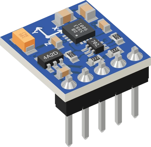
The GY-271 (QMC5883L) compass module runs from the Raspberry Pi Pico's 3V3 and sits on I2C0, SDA on GP4 and SCL on GP5, at address 0x0D. Its pull-ups go to the module's VCC, so 3V3 keeps the bus at the Pico's level; on VBUS they would lift GP4 and GP5 to about 5 V.
Wiring the GY-271 Compass (QMC5883L) to the Raspberry Pi Pico
Pin by pin.
| GY-271 Compass (QMC5883L) | Raspberry Pi Pico |
|---|---|
| VCC | 3V3 |
| GND | GND |
| SDA | GP4 |
| SCL | GP5 |
What to know on the Raspberry Pi Pico
- compass.init() calls Wire.begin() itself. On the Pico, call Wire.setSDA() and Wire.setSCL() before init() if you move the bus off GP4 and GP5.QMC5883LCompass library source, init(); arduino-pico core documentation (Earle Philhower), Wire
- The chip inside runs from 2.16 V to 3.6 V and draws 75 µA at 10 Hz; the module regulates its VCC down, and on 3V3 it is a negligible load for the Pico's rail.QST QMC5883L datasheet Rev A, p. 4
- Keep the module away from the Pico's switching buck-boost regulator and from any motor or servo the Pico drives: a magnetometer reads their fields as heading error.Raspberry Pi Pico datasheet, release 21, p. 20
- If nothing answers at 0x0D, the board may carry an older HMC5883L at 0x1E, which needs another library.Honeywell HMC5883L datasheet Rev E, p. 11
GY-271 Compass (QMC5883L) code for the Raspberry Pi Pico
Compiled for rp2040:rp2040:rpipico on 2026-10-30.
// GY-271 Compass (QMC5883L) on Raspberry Pi Pico: wiring and a free simulation at https://www.tinkered.ai/components/gy-271/raspberry-pi-pico
// lib_deps = mprograms/QMC5883LCompass
#include <QMC5883LCompass.h>

QMC5883LCompass compass;

const char* const POINTS[16] = {"N", "NNE", "NE", "ENE", "E", "ESE", "SE", "SSE", "S", "SSW", "SW", "WSW", "W", "WNW", "NW", "NNW"};

void setup() {
  Serial.begin(9600);
  compass.init();            // Wire.begin(), then continuous 200 Hz, ±8 G
  Serial.println("Compass ready");
}

void loop() {
  compass.read();
  int x = compass.getX();
  int y = compass.getY();
  int z = compass.getZ();

  int heading = compass.getAzimuth();   // -180..179
  if (heading < 0) heading += 360;      // 0..359, clockwise from magnetic north

  // the 16-point name: 22.5° each, N centred on 0
  const char* point = POINTS[(int)((heading + 11.25) / 22.5) % 16];

  Serial.print("heading ");
  Serial.print(heading);
  Serial.print(" ");
  Serial.print(point);
  Serial.print("  x ");
  Serial.print(x);
  Serial.print(" y ");
  Serial.print(y);
  Serial.print(" z ");
  Serial.println(z);
  delay(250);
}
GY-271 Compass (QMC5883L) on the Raspberry Pi Pico: questions
Do I power the GY-271 from 3V3 or VBUS on a Pico?
3V3. The module's 2.2 kOhm pull-ups go to its VCC, so 3V3 keeps SDA and SCL at 3.3 V; on VBUS they would sit near 5 V, above the RP2040's IOVDD + 0.5 V limit (RP2040 datasheet, section 5.5.3.1).
Why is my Pico compass heading wrong?
Keep the board flat and away from magnets, motors and the Pico's own switching regulator (Pico datasheet, p. 20). getAzimuth() returns -180 to 179; the sketch adds 360 to negative values.
Does the Pico see the GY-271 on an I2C scan?
A QMC5883L answers at 0x0D (QST datasheet Rev A, p. 13). A board answering at 0x1E carries an HMC5883L instead.
Keep going
This guide as plain Markdown. /components/gy-271/raspberry-pi-pico.md