TM1638 LED&KEY
An 8-digit 7-segment display, 8 LEDs and 8 push buttons on one board, all driven and scanned by a TM1638 over three wires.
- Display drive10 segments × 8 grids, 8-step brightness
- Key scan8 × 3 matrix
- Supply (VDD)5 V; characterised at 4.5 V to 5.5 V
- Absolute maximumVDD -0.5 V to +7.0 V; inputs -0.5 V to VDD + 0.5 V
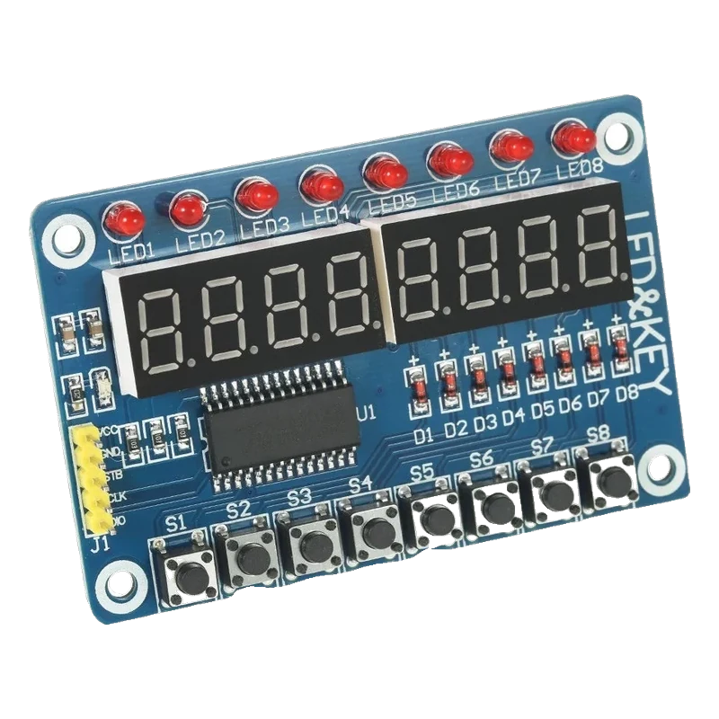
The LED&KEY board puts eight 7-segment digits, eight red LEDs and eight buttons behind one TM1638, which drives 10 segments × 8 grids and scans an 8 × 3 key matrix (Titan Micro TM1638 datasheet, p. 1). It runs from 5 V and talks over STB, CLK and DIO at up to 1 MHz, with DIO an open-drain line pulled up by 10 kΩ (pp. 2, 14, 16). Its inputs need 0.7 × VDD, 3.5 V at 5 V (p. 15), so it wires straight to an Uno but needs a level shifter on an ESP32 or a Pico.
One chip does everything on this board: the TM1638 multiplexes the eight digits and the eight LEDs, sets their brightness in 8 steps, and scans the buttons in the background (Titan Micro TM1638 datasheet, p. 1). The microcontroller only sends what to show and asks which keys are down, which makes the board a quick front panel for timers, counters, test gear and games.
The interface is three wires and not standard SPI: STB frames each transfer, CLK clocks bits, and DIO carries data both ways. When the chip answers a key read, DIO is an N-channel open-drain output that needs a pull-up; the datasheet recommends 10 kΩ (p. 2), and its reference circuit pulls STB, CLK and DIO up to VCC through 10 kΩ each (p. 14).
The TM1638 is a 5 V part, characterised at 4.5 V to 5.5 V with inputs that read high from 0.7 × VDD (p. 15). With the pull-ups at 5 V, a 3.3 V board can neither guarantee a valid high nor accept DIO's 5 V level, so ESP32 and Pico wiring goes through a bidirectional level shifter. The TM1638plus library handles the protocol, text, numbers, LEDs and buttons.
TM1638 LED&KEY pinout
| Pin | Function | Type |
|---|---|---|
| VCC | Supply5 V | power in |
| GND | Ground | power in |
| STB | Strobe (chip select)5 V logic, pulled up | input |
| CLK | Clock5 V logic, pulled up | input |
| DIO | Data in / key data out (open drain)5 V logic, pulled up | bidirectional |
How to wire the TM1638 LED&KEY
Pin by pin, for the board you have.
| TM1638 LED&KEY | Arduino Uno | Note |
|---|---|---|
| VCC | 5V | |
| GND | GND | |
| STB | D4 | |
| CLK | D6 | |
| DIO | D7 |
| TM1638 LED&KEY | ESP32 DevKit V1 | Note |
|---|---|---|
| VCC | VIN (5 V) and the level shifter's HV | |
| GND | GND | |
| STB | GPIO25 (D25) through a BSS138 level shifter (LV = 3V3) | |
| CLK | GPIO26 (D26) through the level shifter | |
| DIO | GPIO27 (D27) through the level shifter |
- DIO is pulled up to the module's 5 V, and the TM1638 needs 3.5 V for a high at 5 V (datasheet, p. 15): a bidirectional BSS138 shifter handles both directions.
| TM1638 LED&KEY | Raspberry Pi Pico | Note |
|---|---|---|
| VCC | VBUS (5 V from USB) and the level shifter's HV | |
| GND | GND | |
| STB | GP2 through a BSS138 level shifter (LV = 3V3(OUT)) | |
| CLK | GP3 through the level shifter | |
| DIO | GP4 through the level shifter |
- Never connect DIO straight to a Pico pin: its pull-up goes to the module's 5 V.
TM1638 LED&KEY code
Every example here compiles for its board.
// TM1638 LED&KEY on Arduino Uno: wiring and a free simulation at https://www.tinkered.ai/components/tm1638-led-key
// TM1638 LED&KEY on an Arduino Uno: STB D4, CLK D6, DIO D7
// Shows a counter; each button lights the LED above it.
#include <TM1638plus.h>

const uint8_t STB = 4;
const uint8_t CLK = 6;
const uint8_t DIO = 7;
TM1638plus tm(STB, CLK, DIO, false); // false: no extra delay needed at 16 MHz

void setup() {
  Serial.begin(115200);
  tm.displayBegin();
  tm.brightness(2); // 0 to 7
  tm.displayText("HELLO");
  delay(1000);
}

void loop() {
  static unsigned long counter = 0;
  static uint8_t lastButtons = 0;
  uint8_t buttons = tm.readButtons(); // bit 0 = S1 ... bit 7 = S8
  for (uint8_t i = 0; i < 8; i++) tm.setLED(i, (buttons >> i) & 1);
  if (buttons != lastButtons) {
    Serial.print(F("Buttons: 0b"));
    Serial.println(buttons, BIN);
    lastButtons = buttons;
  }
  tm.displayIntNum(counter / 10, false, TMAlignTextRight);
  counter++;
  delay(100);
}
// TM1638 LED&KEY on ESP32 DevKit V1: wiring and a free simulation at https://www.tinkered.ai/components/tm1638-led-key
// TM1638 LED&KEY on an ESP32 DevKit V1 through a BSS138 level shifter: STB GPIO25, CLK GPIO26, DIO GPIO27
// Shows a counter; each button lights the LED above it.
#include <TM1638plus.h>

const uint8_t STB = 25;
const uint8_t CLK = 26;
const uint8_t DIO = 27;
TM1638plus tm(STB, CLK, DIO, true); // true: slows the bit timing for a fast MCU

void setup() {
  Serial.begin(115200);
  tm.displayBegin();
  tm.brightness(2);
  tm.displayText("HELLO");
  delay(1000);
}

void loop() {
  static unsigned long counter = 0;
  static uint8_t lastButtons = 0;
  uint8_t buttons = tm.readButtons();
  for (uint8_t i = 0; i < 8; i++) tm.setLED(i, (buttons >> i) & 1);
  if (buttons != lastButtons) {
    Serial.printf("Buttons: 0x%02X\n", buttons);
    lastButtons = buttons;
  }
  tm.displayIntNum(counter / 10, false, TMAlignTextRight);
  counter++;
  delay(100);
}
// TM1638 LED&KEY on Raspberry Pi Pico: wiring and a free simulation at https://www.tinkered.ai/components/tm1638-led-key
// TM1638 LED&KEY on a Raspberry Pi Pico (arduino-pico) through a BSS138 level shifter: STB GP2, CLK GP3, DIO GP4
// Shows a counter; each button lights the LED above it.
#include <TM1638plus.h>

const uint8_t STB = 2;
const uint8_t CLK = 3;
const uint8_t DIO = 4;
TM1638plus tm(STB, CLK, DIO, true); // true: slows the bit timing for a fast MCU

void setup() {
  Serial.begin(115200);
  tm.displayBegin();
  tm.brightness(2);
  tm.displayText("HELLO");
  delay(1000);
}

void loop() {
  static unsigned long counter = 0;
  static uint8_t lastButtons = 0;
  uint8_t buttons = tm.readButtons();
  for (uint8_t i = 0; i < 8; i++) tm.setLED(i, (buttons >> i) & 1);
  if (buttons != lastButtons) {
    Serial.print("Buttons: 0b");
    Serial.println(buttons, BIN);
    lastButtons = buttons;
  }
  tm.displayIntNum(counter / 10, false, TMAlignTextRight);
  counter++;
  delay(100);
}
Before you wire it
- Power the board from 5 V: the TM1638 is characterised at 4.5 V to 5.5 V (Titan Micro TM1638 datasheet, p. 15).
- Put a bidirectional level shifter between the board and a 3.3 V microcontroller; DIO carries data in both directions.
- Set TM1638plus's high-frequency flag to true on ESP32 and RP2040 boards so the bit timing stays under the chip's 1 MHz clock limit (p. 16).
- Keep STB, CLK and DIO wires short; the bus is slow but unshielded.
- Never wire DIO directly to an ESP32 or Pico pin: it is pulled up to the module's 5 V.
- Never drive the inputs above VDD + 0.5 V (p. 14).
- Never treat it as an SPI device on the hardware SPI pins; it uses its own three-wire protocol.
- DIO is open-drain while the chip returns key data, so it needs a pull-up to VCC; the datasheet's reference circuit uses 10 kΩ on STB, CLK and DIO (p. 14), and a BSS138 shifter's own HV-side pull-ups also fill that role.
- readButtons() returns one byte with a bit per button, S1 in bit 0, so several keys pressed at once are all reported.
- Brightness has 8 steps (p. 1); lower levels cut the board's current noticeably and are easier on the eyes indoors.
- A BSS138 four-channel shifter (the common logic level converter board) works here: the TM1638's 1 MHz maximum clock is well within what it passes.
- Several LED&KEY boards can share CLK and DIO with a separate STB line each.
Specifications
- Display drive
- 10 segments × 8 grids, 8-step brightnessTitan Micro TM1638 datasheet, p. 1
- Key scan
- 8 × 3 matrixTitan Micro TM1638 datasheet, p. 1
- Supply (VDD)
- 5 V; characterised at 4.5 V to 5.5 VTitan Micro TM1638 datasheet, pp. 2, 15
- Absolute maximum
- VDD -0.5 V to +7.0 V; inputs -0.5 V to VDD + 0.5 VTitan Micro TM1638 datasheet, p. 14
- Input threshold
- VIH 0.7 × VDD (3.5 V at 5 V), VIL up to 0.3 × VDDTitan Micro TM1638 datasheet, p. 15
- DIO
- N-channel open-drain when outputting; 1 kΩ to 10 kΩ pull-up, 10 kΩ recommendedTitan Micro TM1638 datasheet, p. 2
- Clock
- 1 MHz maximumTitan Micro TM1638 datasheet, p. 16
- Drive current
- Segment outputs source 20 mA to 40 mA, grid outputs sink 140 mATitan Micro TM1638 datasheet, p. 15
From the Titan Micro TM1638 LED driver controller datasheet (English), published by Titan Micro Electronics (TM1638).
Common mistakes
Running it from 3.3 V
The TM1638 is specified at 4.5 V to 5.5 V (Titan Micro datasheet, p. 15). At 3.3 V the digits are dim and keys or segments behave erratically. Power it from 5 V and shift the logic.
DIO straight to a 3.3 V board
DIO is open-drain with a pull-up to VCC (Titan Micro datasheet, pp. 2, 14), so it rises to 5 V when the microcontroller releases it to read the keys. On an ESP32 or Pico that is over the pin's rating; use a bidirectional level shifter.
Garbled digits on a fast board
At 240 MHz or 133 MHz, bit-banged pulses are too short for the TM1638's 1 MHz limit (p. 16). Pass true as the last argument of the TM1638plus constructor.
Mixing up TM1638 and TM1637 code
The TM1637 4-digit modules use two wires and a different protocol. TM1637 libraries do not drive the LED&KEY board; use TM1638plus.
TM1638 LED&KEY questions
Does the TM1638 LED&KEY work with an ESP32?
Yes, through a level shifter. The chip runs at 5 V and reads a high only above 0.7 × VDD (Titan Micro TM1638 datasheet, p. 15), and DIO is pulled up to 5 V, so put a bidirectional BSS138 shifter on STB, CLK and DIO and power the board from VIN.
Which library should I use for the TM1638?
TM1638plus by Gavin Lyons supports the LED&KEY board on AVR, ESP32 and RP2040: displayText(), displayIntNum(), setLED() and readButtons() cover most projects.
How many buttons can the TM1638 read?
The chip scans an 8 × 3 matrix, up to 24 keys (p. 1). The LED&KEY board wires 8 of them, readable as one byte.
TM1638 or TM1637?
The TM1637 drives 4 or 6 digits over two wires and reads a few keys at most. The TM1638 drives 8 digits plus LEDs and scans up to 24 keys over three wires, which suits front panels.
How do I change the brightness?
Call brightness(0) to brightness(7); the TM1638 has 8 brightness steps (p. 1).
Build something with the TM1638 LED&KEY
- Build this
Reaction timer game
Light a random LED and time how fast its button is pressed.
- Build this
Bench countdown timer
Set minutes and seconds with the buttons and count down.
This page as plain Markdown, for ChatGPT, Claude or your own agent. /components/tm1638-led-key.md