nRF24L01+
A low-cost 2.4 GHz radio module with a PCB antenna that links microcontrollers over SPI, with automatic acknowledgements and retries.
- Supply voltage (VCC)1.9 V to 3.6 V (3.0 V typical)
- Absolute maximumVDD 3.6 V; logic inputs -0.3 V to 5.25 V
- 5 V inputs conditionWith inputs above 3.6 V, VDD must be 2.7 V to 3.3 V
- Current11.3 mA TX at 0 dBm, 13.5 mA RX at 2 Mbps, 26 µA standby-I, 900 nA power down
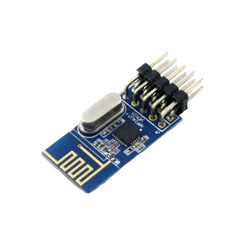
The nRF24L01+ is Nordic's 2.4 GHz transceiver: it runs from 1.9 V to 3.6 V, draws 11.3 mA transmitting at 0 dBm and 13.5 mA receiving at 2 Mbps, and talks SPI at up to 10 Mbps (Nordic nRF24L01+ Product Specification v1.0, pp. 8, 13, 14). Its logic inputs are 5 V tolerant (p. 12), so it wires straight to an Uno's SPI pins, but VCC must come from 3.3 V. Wire GND, VCC, CE, CSN, SCK, MOSI and MISO, add a 10 µF capacitor across VCC and GND, and drive it with the RF24 library.
This is the small module with a zigzag PCB antenna and a 2×4 pin header that makers buy by the handful. It carries Nordic's nRF24L01+ radio, a 16 MHz crystal and the antenna match, nothing more: no regulator and no level shifting. The radio works in the 2.4 GHz band on 126 channels with on-air rates of 250 kbps, 1 Mbps or 2 Mbps (Nordic nRF24L01+ Product Specification v1.0, p. 8).
Its Enhanced ShockBurst engine handles packet framing, CRC, acknowledgements and retransmission in hardware, so a sketch just writes a payload of up to 32 bytes and learns whether the other end received it. One receiver can listen on six pipes at once, which makes it easy to build a star of sensor nodes around one hub. Current is low: 11.3 mA in transmit at 0 dBm, 13.5 mA in receive at 2 Mbps and 900 nA in power down (p. 14).
The weak spot is the supply. The radio needs 1.9 V to 3.6 V, never 5 V on VCC, and its current pulses upset a noisy or long supply line. A 10 µF to 100 µF capacitor soldered across VCC and GND at the module cures most "it only works sometimes" problems. For more range, the PA+LNA version with an external antenna uses the same chip and code.
nRF24L01+ pinout
| Pin | Function | Type |
|---|---|---|
| GND | Ground | power in |
| VCC | Supply1.9 V to 3.6 V | power in |
| CE | Chip enable (TX/RX)5 V tolerant | input |
| CSN | SPI CS (active low)5 V tolerant | input |
| SCK | SPI SCK5 V tolerant | input |
| MOSI | SPI MOSI5 V tolerant | input |
| MISO | SPI MISOVCC level (3.3 V) | output |
| IRQ | Interrupt (active low) | open collector |
How to wire the nRF24L01+
Pin by pin, for the board you have.
| nRF24L01+ | Arduino Uno | Note |
|---|---|---|
| GND | GND | |
| VCC | 3.3V | 10 µF capacitor across VCC and GND at the module. |
| CE | D9 | |
| CSN | D10 | |
| SCK | D13 | |
| MOSI | D11 | |
| MISO | D12 | |
| IRQ | Not connected |
- VCC goes to 3.3V, never 5V. The module's peak of about 13.5 mA fits the Uno's 50 mA 3.3V pin.
| nRF24L01+ | ESP32 DevKit V1 | Note |
|---|---|---|
| GND | GND | |
| VCC | 3V3 | 10 µF capacitor across VCC and GND at the module. |
| CE | GPIO4 (D4) | |
| CSN | GPIO5 (D5) | |
| SCK | GPIO18 (D18) | |
| MOSI | GPIO23 (D23) | |
| MISO | GPIO19 (D19) | |
| IRQ | Not connected |
| nRF24L01+ | Raspberry Pi Pico | Note |
|---|---|---|
| GND | GND | |
| VCC | 3V3(OUT) | 10 µF capacitor across VCC and GND at the module. |
| CE | GP20 | |
| CSN | GP17 | |
| SCK | GP18 | |
| MOSI | GP19 | |
| MISO | GP16 | |
| IRQ | Not connected |
nRF24L01+ code
Every example here compiles for its board.
// nRF24L01+ on Arduino Uno: wiring and a free simulation at https://www.tinkered.ai/components/nrf24l01
// nRF24L01+ on an Arduino Uno: CE D9, CSN D10, SPI on D11/D12/D13
// Flash one board with isSender = true and another with isSender = false.
#include <SPI.h>
#include <RF24.h>

RF24 radio(9, 10); // CE, CSN
const uint8_t address[6] = "NODE1";
const bool isSender = true;
uint32_t counter = 0;

void setup() {
  Serial.begin(115200);
  if (!radio.begin()) {
    Serial.println("nRF24L01+ not responding: check wiring and the 3.3 V supply");
    while (true) {}
  }
  radio.setPALevel(RF24_PA_LOW); // low power for bench tests
  radio.setDataRate(RF24_1MBPS);
  radio.setChannel(76);
  radio.setPayloadSize(sizeof(counter));
  if (isSender) {
    radio.openWritingPipe(address);
    radio.stopListening();
  } else {
    radio.openReadingPipe(1, address);
    radio.startListening();
  }
  Serial.println(isSender ? "Sender ready" : "Receiver ready");
}

void loop() {
  if (isSender) {
    bool ok = radio.write(&counter, sizeof(counter));
    Serial.print("Sent ");
    Serial.print(counter);
    Serial.println(ok ? " (acknowledged)" : " (no acknowledgement)");
    counter++;
    delay(1000);
  } else if (radio.available()) {
    uint32_t value;
    radio.read(&value, sizeof(value));
    Serial.print("Received ");
    Serial.println(value);
  }
}
// nRF24L01+ on ESP32 DevKit V1: wiring and a free simulation at https://www.tinkered.ai/components/nrf24l01
// nRF24L01+ on an ESP32 DevKit V1: CE GPIO4, CSN GPIO5, VSPI on GPIO18/19/23
// Flash one board with isSender = true and another with isSender = false.
#include <SPI.h>
#include <RF24.h>

RF24 radio(4, 5); // CE, CSN
const uint8_t address[6] = "NODE1";
const bool isSender = true;
uint32_t counter = 0;

void setup() {
  Serial.begin(115200);
  if (!radio.begin()) {
    Serial.println("nRF24L01+ not responding: check wiring and the 3.3 V supply");
    while (true) { delay(100); }
  }
  radio.setPALevel(RF24_PA_LOW);
  radio.setDataRate(RF24_1MBPS);
  radio.setChannel(76);
  radio.setPayloadSize(sizeof(counter));
  if (isSender) {
    radio.openWritingPipe(address);
    radio.stopListening();
  } else {
    radio.openReadingPipe(1, address);
    radio.startListening();
  }
  Serial.println(isSender ? "Sender ready" : "Receiver ready");
}

void loop() {
  if (isSender) {
    bool ok = radio.write(&counter, sizeof(counter));
    Serial.printf("Sent %lu %s\n", (unsigned long)counter, ok ? "(acknowledged)" : "(no acknowledgement)");
    counter++;
    delay(1000);
  } else if (radio.available()) {
    uint32_t value;
    radio.read(&value, sizeof(value));
    Serial.printf("Received %lu\n", (unsigned long)value);
  }
}
// nRF24L01+ on Raspberry Pi Pico: wiring and a free simulation at https://www.tinkered.ai/components/nrf24l01
// nRF24L01+ on a Raspberry Pi Pico (arduino-pico): CE GP20, CSN GP17, SPI0 on GP16/18/19
// Flash one board with isSender = true and another with isSender = false.
#include <SPI.h>
#include <RF24.h>

RF24 radio(20, 17); // CE, CSN
const uint8_t address[6] = "NODE1";
const bool isSender = true;
uint32_t counter = 0;

void setup() {
  Serial.begin(115200);
  SPI.setRX(16);
  SPI.setSCK(18);
  SPI.setTX(19);
  if (!radio.begin()) {
    Serial.println("nRF24L01+ not responding: check wiring and the 3.3 V supply");
    while (true) { delay(100); }
  }
  radio.setPALevel(RF24_PA_LOW);
  radio.setDataRate(RF24_1MBPS);
  radio.setChannel(76);
  radio.setPayloadSize(sizeof(counter));
  if (isSender) {
    radio.openWritingPipe(address);
    radio.stopListening();
  } else {
    radio.openReadingPipe(1, address);
    radio.startListening();
  }
  Serial.println(isSender ? "Sender ready" : "Receiver ready");
}

void loop() {
  if (isSender) {
    bool ok = radio.write(&counter, sizeof(counter));
    Serial.print("Sent ");
    Serial.print(counter);
    Serial.println(ok ? " (acknowledged)" : " (no acknowledgement)");
    counter++;
    delay(1000);
  } else if (radio.available()) {
    uint32_t value;
    radio.read(&value, sizeof(value));
    Serial.print("Received ");
    Serial.println(value);
  }
}
Before you wire it
- Power VCC from 3.3 V; the supply range is 1.9 V to 3.6 V (Nordic Product Specification v1.0, p. 13).
- Solder or plug a 10 µF to 100 µF capacitor across VCC and GND right at the module.
- Use the same channel, data rate, address and payload size on both ends.
- Keep VCC between 2.7 V and 3.3 V when the SPI lines come from a 5 V board, as the 5 V tolerance requires (p. 20).
- Keep the PCB antenna clear of metal, wires and the breadboard's own rails for best range.
- Never connect VCC to 5 V: the absolute maximum is 3.6 V (p. 12).
- Never test two modules a few centimetres apart at full power: the receivers saturate; use RF24_PA_LOW or MIN on the bench.
- Never share the CSN pin with another SPI device.
- The header is 2 × 4 at 2.54 mm and does not fit a breadboard; use female jumpers or a socket adapter, which often adds a regulator so the module can run from 5 V.
- MISO is driven at the module's VCC level; ESP32 and Pico read it directly, and a 5 V Uno accepts it as a HIGH on its SPI input in practice.
- IRQ is active low and only needed for interrupt-driven code; RF24 polls the status register when it is left open.
- At 250 kbps the receiver gains about 9 dB of sensitivity over 1 Mbps (-94 dBm against -85 dBm, p. 16), the easiest way to more range without changing hardware.
- Wi-Fi shares the 2.4 GHz band; channels above 100 (2.500 GHz and up) usually sit clear of Wi-Fi traffic.
Specifications
- Supply voltage (VCC)
- 1.9 V to 3.6 V (3.0 V typical)Nordic nRF24L01+ Product Specification v1.0, Table 3, p. 13
- Absolute maximum
- VDD 3.6 V; logic inputs -0.3 V to 5.25 VNordic nRF24L01+ Product Specification v1.0, Table 2, p. 12
- 5 V inputs condition
- With inputs above 3.6 V, VDD must be 2.7 V to 3.3 VNordic nRF24L01+ Product Specification v1.0, pp. 13, 20
- Current
- 11.3 mA TX at 0 dBm, 13.5 mA RX at 2 Mbps, 26 µA standby-I, 900 nA power downNordic nRF24L01+ Product Specification v1.0, pp. 1, 14
- Air data rates
- 250 kbps, 1 Mbps, 2 MbpsNordic nRF24L01+ Product Specification v1.0, p. 8
- Output power
- 0, -6, -12 or -18 dBm (programmable)Nordic nRF24L01+ Product Specification v1.0, p. 8
- Receiver sensitivity
- -94 dBm at 250 kbps, -85 dBm at 1 Mbps, -82 dBm at 2 MbpsNordic nRF24L01+ Product Specification v1.0, p. 16
- Channels
- 126 RF channels in the 2.4 GHz band, 1 MHz spacing (2 MHz at 2 Mbps)Nordic nRF24L01+ Product Specification v1.0, p. 8
- SPI clock
- Up to 10 MbpsNordic nRF24L01+ Product Specification v1.0, p. 8
From the Nordic Semiconductor nRF24L01+ Product Specification v1.0, published by Nordic Semiconductor.
Common mistakes
Powering it from 5 V
VCC tops out at 3.6 V (Nordic Product Specification v1.0, p. 12). A module run from 5 V may work for a moment and then fail for good. Only the signal pins are 5 V tolerant.
No capacitor on VCC
Transmit pulses on a long jumper from the board's 3.3 V pin make the radio brown out, which shows up as sends that are never acknowledged or a begin() that fails at random. A 10 µF capacitor across VCC and GND at the module is the standard cure.
Mismatched settings on the two ends
Channel, data rate, address, payload size and CRC length must match exactly, or nothing is received. Keep them in one shared block of code that both boards compile.
Swapping CE and CSN
CE switches the radio between standby and active; CSN selects it on the SPI bus. Swapped, begin() can still see a chip but nothing transmits. Check them against the constructor RF24(CE, CSN).
nRF24L01+ questions
Is the nRF24L01+ 5 V tolerant?
Its logic inputs are, up to 5.25 V, but VCC is not: the supply must stay at 1.9 V to 3.6 V, and with 5 V signals it must be 2.7 V to 3.3 V (Nordic Product Specification v1.0, pp. 12, 13, 20). So on an Uno, power it from 3.3V and connect the SPI pins directly.
What range does the nRF24L01+ PCB antenna module reach?
Range depends on data rate, power and surroundings. At 0 dBm the receiver hears down to -94 dBm at 250 kbps (p. 16), which typically gives tens of metres indoors. For hundreds of metres, use the PA+LNA version with an external antenna.
Which library should I use?
RF24 (nrf24/RF24) is the maintained library for Arduino, ESP32 and RP2040 boards. It wraps the auto-acknowledgement, retries and pipes, and its RF24Network and RF24Mesh add-ons build multi-node networks.
Why does radio.write() return false?
No acknowledgement came back. Check the receiver is listening on the same address, channel, data rate and payload size, that both modules have a capacitor on VCC, and that they are not so close they saturate each other at high power.
nRF24L01+ or HC-12: which should I choose?
The nRF24L01+ is cheaper, faster (up to 2 Mbps) and runs on SPI with hardware acknowledgements, but its 2.4 GHz signal goes less far through walls. The HC-12 is a 433 MHz serial radio with longer range at low data rates and no protocol work.
How many nRF24L01+ modules can talk to one receiver?
One receiver listens on six data pipes at once, each with its own address. RF24Network extends that to a tree of many nodes.
Build something with the nRF24L01+
- Build this
Wireless weather node
An outdoor Uno sends temperature and humidity every minute to an indoor receiver.
- Build this
Two-axis radio remote
A joystick on one board steers two servos on another.
This page as plain Markdown, for ChatGPT, Claude or your own agent. /components/nrf24l01.md