Nokia 5110 LCD
The 84 × 48 pixel monochrome graphic LCD from the Nokia 5110 phone, on a backlit breakout driven by a PCD8544 over a write-only SPI bus.
- Resolution84 × 48 pixels, 48 × 84 bit display RAM
- Logic supply (VDD)2.7 V to 3.3 V
- Input voltage limit-0.5 V to VDD + 0.5 V on all inputs
- Input thresholdHigh from 0.7 × VDD, low up to 0.3 × VDD
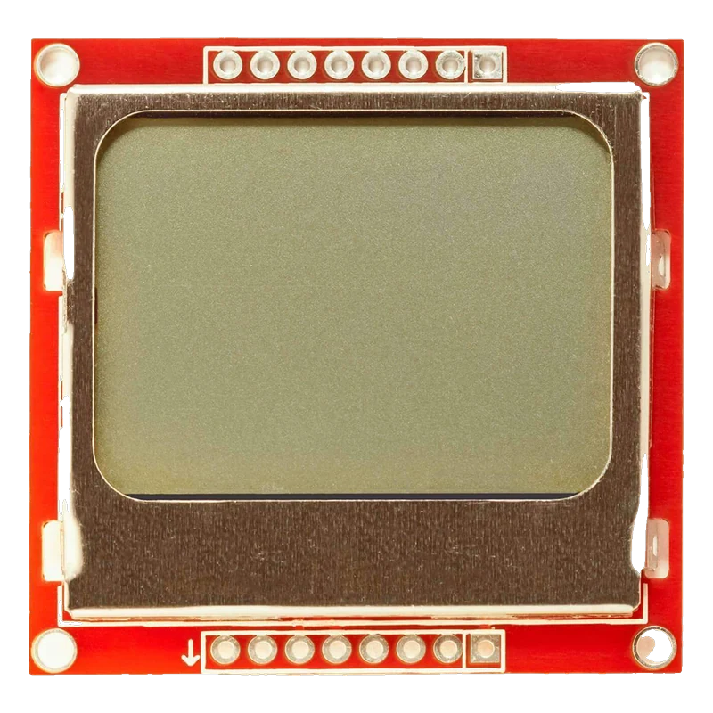
The Nokia 5110 module is an 84 × 48 pixel monochrome LCD driven by the Philips PCD8544, whose logic runs at 2.7 V to 3.3 V and draws about 240 µA (PCD8544 product specification, pp. 3, 18). It takes data over a write-only SPI-style bus at up to 4.0 Mbit/s on pins RST, CE, DC, DIN and CLK (p. 3), with VCC, LIGHT and GND for power and backlight. Its inputs must stay below VDD + 0.5 V (p. 17), so a 5 V Uno needs a 3.3 V buffer, while an ESP32 or a Pico wires directly.
This is the screen from the Nokia 5110 and 3310 phones, mounted on a small board with four backlight LEDs and two 8-pin headers. The PCD8544 controller drives the 48 rows and 84 columns from its own 48 × 84 bit RAM and generates the LCD's 6 V to 8.5 V bias internally (PCD8544 product specification, p. 3), so only a 3.3 V supply is needed.
It is one of the lowest-power graphic displays a maker can buy: the controller draws about 240 µA in normal mode and 1.5 µA in power-down (p. 18), and without the backlight the reflective LCD stays readable in daylight. That makes it a favourite for battery projects, retro games and small instruments.
The bus is write-only SPI: CLK and DIN carry data, CE selects the chip, DC chooses command or data, and RST resets it. The PCD8544 is a 3.3 V part whose inputs read high from 0.7 × VDD and must not exceed VDD + 0.5 V (pp. 17 to 18). The Adafruit PCD8544 library handles the init, contrast and an 84 × 48 frame buffer of 504 bytes.
Nokia 5110 LCD pinout
| Pin | Function | Type |
|---|---|---|
| RST | Reset (active low)3.3 V only | input |
| CE | SPI CS (active low)3.3 V only | input |
| DC | Data / command select3.3 V only | input |
| DIN | SPI MOSI3.3 V only | input |
| CLK | SPI SCK3.3 V only | input |
| VCC | Supply2.7 V to 3.3 V | power in |
| LIGHT | Backlight | input |
| GND | Ground | power in |
How to wire the Nokia 5110 LCD
Pin by pin, for the board you have.
| Nokia 5110 LCD | Arduino Uno | Note |
|---|---|---|
| VCC | 3.3V | |
| GND | GND | |
| CLK | D13 through a 74HC4050 buffer powered from 3.3 V | |
| DIN | D11 through the 74HC4050 | |
| DC | D9 through the 74HC4050 | |
| CE | D10 through the 74HC4050 | |
| RST | D8 through the 74HC4050 | |
| LIGHT | GND (backlight on, red board) |
- 5 V signals exceed the PCD8544's VDD + 0.5 V input limit (product specification, p. 17); buffer all five signal lines down to 3.3 V.
| Nokia 5110 LCD | ESP32 DevKit V1 | Note |
|---|---|---|
| VCC | 3V3 | |
| GND | GND | |
| CLK | GPIO18 (D18) | |
| DIN | GPIO23 (D23) | |
| DC | GPIO16 (RX2) | |
| CE | GPIO5 (D5) | |
| RST | GPIO17 (TX2) | |
| LIGHT | GND (backlight on, red board) |
| Nokia 5110 LCD | Raspberry Pi Pico | Note |
|---|---|---|
| VCC | 3V3(OUT) | |
| GND | GND | |
| CLK | GP18 | |
| DIN | GP19 | |
| DC | GP21 | |
| CE | GP17 | |
| RST | GP20 | |
| LIGHT | GND (backlight on, red board) |
Nokia 5110 LCD code
Every example here compiles for its board.
// Nokia 5110 LCD on Arduino Uno: wiring and a free simulation at https://www.tinkered.ai/components/nokia-5110-lcd
// Nokia 5110 (PCD8544) on an Arduino Uno through a 74HC4050: CLK D13, DIN D11, DC D9, CE D10, RST D8
#include <SPI.h>
#include <Adafruit_GFX.h>
#include <Adafruit_PCD8544.h>

Adafruit_PCD8544 display(9, 10, 8); // DC, CE, RST on hardware SPI

void setup() {
  Serial.begin(115200);
  display.begin();
  display.setContrast(50); // raise or lower if the screen is blank or all dark
  display.clearDisplay();
  display.setTextSize(1);
  display.setTextColor(BLACK);
  display.setCursor(0, 0);
  display.println(F("Nokia 5110"));
  display.println(F("84 x 48 LCD"));
  display.display();
  Serial.println(F("LCD ready"));
  delay(1000);
}

void loop() {
  static unsigned long seconds = 0;
  display.clearDisplay();
  display.setTextSize(1);
  display.setCursor(0, 0);
  display.println(F("Uptime"));
  display.setTextSize(2);
  display.setCursor(0, 16);
  display.print(seconds);
  display.display();
  Serial.print(F("Uptime: "));
  Serial.println(seconds);
  seconds++;
  delay(1000);
}
// Nokia 5110 LCD on ESP32 DevKit V1: wiring and a free simulation at https://www.tinkered.ai/components/nokia-5110-lcd
// Nokia 5110 (PCD8544) on an ESP32 DevKit V1: CLK GPIO18, DIN GPIO23, DC GPIO16, CE GPIO5, RST GPIO17
#include <SPI.h>
#include <Adafruit_GFX.h>
#include <Adafruit_PCD8544.h>

Adafruit_PCD8544 display(16, 5, 17); // DC, CE, RST on hardware SPI

void setup() {
  Serial.begin(115200);
  display.begin();
  display.setContrast(50);
  display.clearDisplay();
  display.setTextSize(1);
  display.setTextColor(BLACK);
  display.setCursor(0, 0);
  display.println("Nokia 5110");
  display.println("84 x 48 LCD");
  display.display();
  Serial.println("LCD ready");
  delay(1000);
}

void loop() {
  static unsigned long seconds = 0;
  display.clearDisplay();
  display.setTextSize(1);
  display.setCursor(0, 0);
  display.println("Uptime");
  display.setTextSize(2);
  display.setCursor(0, 16);
  display.print(seconds);
  display.display();
  Serial.printf("Uptime: %lu s\n", seconds);
  seconds++;
  delay(1000);
}
// Nokia 5110 LCD on Raspberry Pi Pico: wiring and a free simulation at https://www.tinkered.ai/components/nokia-5110-lcd
// Nokia 5110 (PCD8544) on a Raspberry Pi Pico (arduino-pico): CLK GP18, DIN GP19, DC GP21, CE GP17, RST GP20
#include <SPI.h>
#include <Adafruit_GFX.h>
#include <Adafruit_PCD8544.h>

Adafruit_PCD8544 display(21, 17, 20); // DC, CE, RST on hardware SPI

void setup() {
  Serial.begin(115200);
  SPI.setSCK(18);
  SPI.setTX(19);
  display.begin();
  display.setContrast(50);
  display.clearDisplay();
  display.setTextSize(1);
  display.setTextColor(BLACK);
  display.setCursor(0, 0);
  display.println("Nokia 5110");
  display.println("84 x 48 LCD");
  display.display();
  Serial.println("LCD ready");
  delay(1000);
}

void loop() {
  static unsigned long seconds = 0;
  display.clearDisplay();
  display.setTextSize(1);
  display.setCursor(0, 0);
  display.println("Uptime");
  display.setTextSize(2);
  display.setCursor(0, 16);
  display.print(seconds);
  display.display();
  Serial.print("Uptime: ");
  Serial.println(seconds);
  seconds++;
  delay(1000);
}
Before you wire it
- Power VCC from 3.3 V: the PCD8544's logic range is 2.7 V to 3.3 V (product specification, p. 3).
- Keep RST, CE, DC, DIN and CLK at 3.3 V logic, below the VDD + 0.5 V input limit (p. 17).
- Tune the contrast with setContrast() for your module; the right value varies from board to board.
- Call display() after drawing: the library draws into a 504-byte buffer first.
- Never connect VCC to 5 V.
- Never drive the signal lines straight from a 5 V Uno.
- Never exceed 4.0 Mbit/s on the clock (p. 3); the library's hardware SPI speed respects this.
- The PCD8544 generates its LCD bias of 6.0 V to 8.5 V internally (p. 3), so VCC and GND are the only supply connections.
- A 74HC4050 hex buffer powered from 3.3 V is a tidy level shifter: its inputs take 5 V and it has enough channels for all five signals.
- The red boards light their four backlight LEDs when LIGHT is pulled to GND; other versions switch them on with LIGHT high. Drive LIGHT through a transistor or a PWM pin to dim it.
- Contrast drifts with temperature and module batch; if text is invisible or the screen is solid dark, sweep setContrast() from about 30 to 70.
- The display is readable without its backlight, so leave LIGHT unconnected on battery projects for the lowest current.
Specifications
- Resolution
- 84 × 48 pixels, 48 × 84 bit display RAMPhilips PCD8544 product specification (1999 Apr 12), p. 3
- Logic supply (VDD)
- 2.7 V to 3.3 VPhilips PCD8544 product specification, p. 3
- Input voltage limit
- -0.5 V to VDD + 0.5 V on all inputsPhilips PCD8544 product specification, limiting values, p. 17
- Input threshold
- High from 0.7 × VDD, low up to 0.3 × VDDPhilips PCD8544 product specification, p. 18
- Serial interface
- Up to 4.0 Mbit/s, write onlyPhilips PCD8544 product specification, p. 3
- Supply current
- 240 µA typical (normal mode, VDD 2.85 V), 1.5 µA in power-downPhilips PCD8544 product specification, p. 18
- LCD bias
- 6.0 V to 8.5 V generated on chipPhilips PCD8544 product specification, p. 3
- Operating temperature
- -25 °C to +70 °CPhilips PCD8544 product specification, p. 17
From the Philips PCD8544 48 × 84 pixels matrix LCD controller/driver, product specification 1999 Apr 12, published by Philips Semiconductors (PCD8544).
Common mistakes
Feeding 5 V logic
Many tutorials wire the Nokia 5110 straight to an Uno and it may work for a while. The PCD8544's inputs are limited to VDD + 0.5 V (product specification, p. 17), so 5 V signals overstress it; buffer them to 3.3 V.
Blank or black screen from the wrong contrast
With contrast too low the screen looks empty; too high it turns solid dark. Adjust setContrast() in small steps until text is crisp.
Backlight never lights
On the red boards, LIGHT has to go to GND, not to VCC, for the backlight LEDs to light. If one way does nothing, try the other.
Pin order differs between boards
Red and blue Nokia 5110 boards print their pins in different orders. Wire by the printed names, not by position.
Nokia 5110 LCD questions
Is the Nokia 5110 LCD 5 V tolerant?
No. The PCD8544 runs at 2.7 V to 3.3 V and its inputs must stay below VDD + 0.5 V (product specification, pp. 3, 17). On a 5 V board, power it from 3.3 V and buffer the signals; on an ESP32 or a Pico, wire it directly.
What library drives the Nokia 5110?
Adafruit's PCD8544 library with Adafruit GFX, which supports hardware and software SPI and an 84 × 48 frame buffer. U8g2 also supports the PCD8544.
How much current does it draw?
The controller takes about 240 µA and 1.5 µA in power-down (product specification, p. 18). The backlight LEDs draw far more than the controller, so switch them off when not needed.
Why is my Nokia 5110 screen blank?
Check contrast first, then wiring: CE and DC swapped, CLK and DIN on the wrong pins, or RST left floating all give a blank screen. Make sure the constructor's pins match the table and display() is called.
Nokia 5110 or SSD1306 OLED?
The Nokia LCD uses far less power and stays readable in sunlight without its backlight. The 128 × 64 OLED has more pixels, higher contrast and needs only two I2C wires.
Build something with the Nokia 5110 LCD
- Build this
Retro snake game
Classic Snake on the screen it was made for.
- Build this
Battery thermometer
Temperature and humidity on a display that runs for months.
This page as plain Markdown, for ChatGPT, Claude or your own agent. /components/nokia-5110-lcd.md