IRF520 MOSFET driver module
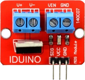
A breakout board that puts the IRF520 behind screw terminals and a gate resistor, used to PWM or switch 12V and 24V DC loads such as LED strips, small motors, pumps, and solenoids from a single microcontroller pin.
N-channel enhancement-mode power MOSFET in a TO-220 package, rated 100V and 9.2A for switching DC loads.
The IRF520 is an N-channel enhancement-mode power MOSFET supplied in a through-hole TO-220AB package. It blocks up to 100V drain-to-source, carries a continuous drain current of 9.2A at 25C, and has a drain-source on-resistance of about 0.27 ohm. It is most often used as a low-side switch, letting a small control signal turn a larger DC load on and off.
Its gate threshold voltage is roughly 2V to 4V, so it begins conducting with a fairly low signal, but that 0.27 ohm on-resistance is only specified with 10V applied at the gate. Driven directly from a 5V or 3.3V microcontroller pin the device only partially turns on, so it works well for lighter loads or for setups where a dedicated gate driver or a 10V rail provides full enhancement.
The three legs are Gate, Drain, and Source, and the metal tab is internally connected to the Drain. Like most power MOSFETs it contains an intrinsic body diode from Source to Drain, which conducts if the drain is pulled below the source.
| Pin | Function | Type |
|---|---|---|
S Source | Passive | Passive |
G Gate | Analog | Digital input |
D Drain | Passive | Passive |
Verified from the Tinkered component library.
The low threshold voltage tempts people to drive it straight from a 5V pin and expect the full 9.2A. On-resistance is only rated at a 10V gate, so at 5V the channel is only partly on, the part heats up, and it cannot pass its rated current.
A MOSFET gate is a capacitor. If the control pin floats (during reset, boot, or a disconnected wire) the gate can hold charge and leave the load in an undefined state. A 10k pull-down from Gate to Source keeps it firmly off.
Switching a motor, solenoid, or relay coil generates a voltage spike that can exceed the 100V rating or damage nearby logic. Always add a flyback diode across the inductive load.
With the printed label facing you and the legs pointing down, the pins are Gate, Drain, Source from left to right, and the tab is Drain. Swapping them, especially Gate and Source, leaves the device stuck off or shorts the load.
A bare TO-220 in still air can only dissipate a few watts. The 60W figure and the 9.2A current assume a proper heatsink, so plan cooling for anything beyond light loads.
A breakout board that puts the IRF520 behind screw terminals and a gate resistor, used to PWM or switch 12V and 24V DC loads such as LED strips, small motors, pumps, and solenoids from a single microcontroller pin.
Driving the gate with an analogWrite PWM signal to dim a 12V LED strip or vary the speed of a small DC motor, keeping high-current switching off the Arduino pins.

resistor-220Custom resistance values supported

resistor-1kCustom resistance values supported

resistor-10kCustom resistance values supported
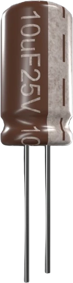
capacitor-ceramicCustom capacitance values supported
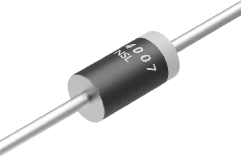
diode-1n4007General-purpose rectifier
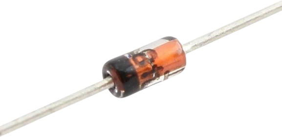
diode-1n4148Fast switching diode
Drop the IRF520 MOSFET into a circuit, write firmware, and simulate it in your browser, then deploy to real hardware. All in one editable Tinkered project.