MAX31865
An RTD-to-digital converter breakout for PT100 and PT1000 platinum temperature probes in 2-, 3- or 4-wire setups, read over SPI with fault detection.
- Chip supplyVDD and DVDD 3.0 V to 3.6 V
- Absolute maximum-0.3 V to 4.0 V on VDD and DVDD; RTD inputs protected to ±45 V
- Resolution15-bit ADC, 0.03125 °C nominal
- Accuracy0.5 °C (0.05 % of full scale) max over all operating conditions
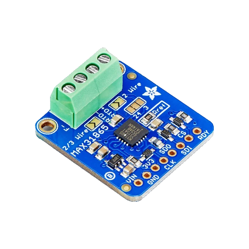
The MAX31865 converts a platinum RTD (PT100 to PT1000) to a 15-bit reading with 0.03125 °C nominal resolution and 0.5 °C total accuracy over all operating conditions, in 21 ms at most, with open and short fault detection and ±45 V input protection (Maxim MAX31865 datasheet Rev 3, p. 1). It talks SPI up to 5 MHz and runs from 3.0 V to 3.6 V (pp. 2, 4). Adafruit's breakout adds a regulator and level shifting on every pin, so VIN takes 3 V to 5 V, and uses a 430 Ω reference for PT100 (4300 Ω for PT1000).
An RTD is a resistor made of platinum whose resistance rises predictably with temperature: 100 Ω at 0 °C for a PT100. The MAX31865 drives a bias current through the probe and a precision reference resistor, and its 15-bit ADC reports the ratio, which the library turns into resistance and then degrees (Maxim datasheet Rev 3, p. 1). Accuracy is 0.5 °C (0.05 % of full scale) over all operating conditions, far better than a thermocouple.
It supports 2-, 3- and 4-wire probes, so lead resistance can be cancelled, and it flags an open element, a short and over or under voltage on its inputs, which are protected to ±45 V (p. 1). Conversion takes 21 ms in continuous mode with the 50 Hz filter (20 ms typical) and is a little faster with 60 Hz filtering (p. 3).
The chip runs from 3.0 V to 3.6 V and draws 2 mA with the bias on (pp. 2 to 3). Adafruit's breakout carries a 3.3 V regulator and level shifting on all inputs, so it works on 3 V and 5 V boards; it ships set for 4-wire probes and solder jumpers select 3-wire or 2-wire (Adafruit guide, pp. 5 to 8).
MAX31865 pinout
| Pin | Function | Type |
|---|---|---|
| VIN | Vin3 V to 5 V, equal to your board's logic level | power in |
| 3Vo | 3Vo3.3 V | power out |
| GND | GND | power in |
| SCK | SPI SCKLevel shifted | input |
| SDO | SPI MISO | output |
| SDI | SPI MOSILevel shifted | input |
| CS | SPI CS (active low)Level shifted | input |
| RDY | Data ready (active low) | output |
| RTD | RTD connection | passive |
How to wire the MAX31865
Pin by pin, for the board you have.
| MAX31865 | Arduino Uno | Note |
|---|---|---|
| VIN | 5V | |
| GND | GND | |
| SCK | D13 | |
| SDO | D12 | |
| SDI | D11 | |
| CS | D10 |
- The sketch is set for a 3-wire PT100: solder the 2/3 Wire jumper closed, cut the trace on the left side of the 2-way jumper above Rref and solder its right side, labelled 3 (Adafruit guide, p. 8). For a 4-wire probe change nothing and use MAX31865_4WIRE.
| MAX31865 | ESP32 DevKit V1 | Note |
|---|---|---|
| VIN | 3V3 | |
| GND | GND | |
| SCK | GPIO18 (D18) | |
| SDO | GPIO19 (D19) | |
| SDI | GPIO23 (D23) | |
| CS | GPIO5 (D5) | VSPI's default CS. GPIO5 is a strapping pin that must be high at boot; CS idles high, so boot is unaffected. |
- Power VIN from 3V3 so SDO stays at 3.3 V. The sketch is set for a 3-wire PT100; see the jumper note in the Uno table.
| MAX31865 | Raspberry Pi Pico | Note |
|---|---|---|
| VIN | 3V3(OUT) | |
| GND | GND | |
| SCK | GP18 | |
| SDO | GP16 | |
| SDI | GP19 | |
| CS | GP17 |
- Power VIN from 3V3(OUT), not VBUS. The sketch is set for a 3-wire PT100; see the jumper note in the Uno table.
MAX31865 code
Every example here compiles for its board.
// MAX31865 on Arduino Uno: wiring and a free simulation at https://www.tinkered.ai/components/max31865
// MAX31865 on an Arduino Uno: VIN 5V, CLK D13, SDO D12, SDI D11, CS D10 (hardware SPI)
#include <SPI.h>
#include <Adafruit_MAX31865.h>

const int PIN_CS = 10;
const float RREF = 430.0;      // reference resistor on Adafruit's PT100 board (4300.0 for PT1000)
const float RNOMINAL = 100.0;  // PT100 at 0 C (1000.0 for PT1000)

Adafruit_MAX31865 rtd(PIN_CS);  // hardware SPI

void setup() {
  Serial.begin(115200);
  if (!rtd.begin(MAX31865_3WIRE)) {  // match the jumpers: MAX31865_2WIRE, _3WIRE or _4WIRE
    Serial.println("MAX31865 did not start. Check wiring.");
    while (true) delay(10);
  }
  Serial.println("MAX31865 ready, PT100 3-wire");
}

void loop() {
  uint16_t raw = rtd.readRTD();
  float ohms = RREF * raw / 32768.0;
  float tempC = rtd.temperature(RNOMINAL, RREF);
  Serial.print("RTD: ");
  Serial.print(ohms, 2);
  Serial.print(" ohm   Temperature: ");
  Serial.print(tempC, 2);
  Serial.println(" C");
  uint8_t fault = rtd.readFault();
  if (fault) {
    Serial.print("Fault 0x");
    Serial.println(fault, HEX);
    if (fault & MAX31865_FAULT_HIGHTHRESH) Serial.println("  RTD high threshold (open element?)");
    if (fault & MAX31865_FAULT_RTDINLOW) Serial.println("  RTDIN- below 0.85 x VBIAS (open wire?)");
    if (fault & MAX31865_FAULT_OVUV) Serial.println("  Over or under voltage");
    rtd.clearFault();
  }
  delay(1000);
}
// MAX31865 on ESP32 DevKit V1: wiring and a free simulation at https://www.tinkered.ai/components/max31865
// MAX31865 on an ESP32 DevKit V1: VIN 3V3, CLK GPIO18, SDO GPIO19, SDI GPIO23, CS GPIO5 (VSPI)
#include <SPI.h>
#include <Adafruit_MAX31865.h>

const int PIN_CS = 5;
const float RREF = 430.0;      // reference resistor on Adafruit's PT100 board (4300.0 for PT1000)
const float RNOMINAL = 100.0;  // PT100 at 0 C (1000.0 for PT1000)

Adafruit_MAX31865 rtd(PIN_CS);  // hardware SPI

void setup() {
  Serial.begin(115200);
  if (!rtd.begin(MAX31865_3WIRE)) {  // match the jumpers: MAX31865_2WIRE, _3WIRE or _4WIRE
    Serial.println("MAX31865 did not start. Check wiring.");
    while (true) delay(10);
  }
  Serial.println("MAX31865 ready, PT100 3-wire");
}

void loop() {
  uint16_t raw = rtd.readRTD();
  float ohms = RREF * raw / 32768.0;
  float tempC = rtd.temperature(RNOMINAL, RREF);
  Serial.print("RTD: ");
  Serial.print(ohms, 2);
  Serial.print(" ohm   Temperature: ");
  Serial.print(tempC, 2);
  Serial.println(" C");
  uint8_t fault = rtd.readFault();
  if (fault) {
    Serial.print("Fault 0x");
    Serial.println(fault, HEX);
    if (fault & MAX31865_FAULT_HIGHTHRESH) Serial.println("  RTD high threshold (open element?)");
    if (fault & MAX31865_FAULT_RTDINLOW) Serial.println("  RTDIN- below 0.85 x VBIAS (open wire?)");
    if (fault & MAX31865_FAULT_OVUV) Serial.println("  Over or under voltage");
    rtd.clearFault();
  }
  delay(1000);
}
// MAX31865 on Raspberry Pi Pico: wiring and a free simulation at https://www.tinkered.ai/components/max31865
// MAX31865 on a Raspberry Pi Pico (arduino-pico): VIN 3V3(OUT), CLK GP18, SDO GP16, SDI GP19, CS GP17 (SPI0)
#include <SPI.h>
#include <Adafruit_MAX31865.h>

const int PIN_CS = 17;
const float RREF = 430.0;      // reference resistor on Adafruit's PT100 board (4300.0 for PT1000)
const float RNOMINAL = 100.0;  // PT100 at 0 C (1000.0 for PT1000)

Adafruit_MAX31865 rtd(PIN_CS);  // hardware SPI

void setup() {
  Serial.begin(115200);
  if (!rtd.begin(MAX31865_3WIRE)) {  // match the jumpers: MAX31865_2WIRE, _3WIRE or _4WIRE
    Serial.println("MAX31865 did not start. Check wiring.");
    while (true) delay(10);
  }
  Serial.println("MAX31865 ready, PT100 3-wire");
}

void loop() {
  uint16_t raw = rtd.readRTD();
  float ohms = RREF * raw / 32768.0;
  float tempC = rtd.temperature(RNOMINAL, RREF);
  Serial.print("RTD: ");
  Serial.print(ohms, 2);
  Serial.print(" ohm   Temperature: ");
  Serial.print(tempC, 2);
  Serial.println(" C");
  uint8_t fault = rtd.readFault();
  if (fault) {
    Serial.print("Fault 0x");
    Serial.println(fault, HEX);
    if (fault & MAX31865_FAULT_HIGHTHRESH) Serial.println("  RTD high threshold (open element?)");
    if (fault & MAX31865_FAULT_RTDINLOW) Serial.println("  RTDIN- below 0.85 x VBIAS (open wire?)");
    if (fault & MAX31865_FAULT_OVUV) Serial.println("  Over or under voltage");
    rtd.clearFault();
  }
  delay(1000);
}
Before you wire it
- Set the solder jumpers to match the probe (2, 3 or 4 wires) and pass the same setting to begin() (Adafruit guide, pp. 7 to 8).
- Use RREF 430 and RNOMINAL 100 for the PT100 board, 4300 and 1000 for the PT1000 board (guide, p. 5).
- Check readFault() and call clearFault() after handling a fault.
- Choose the 50 Hz or 60 Hz filter to match your mains (datasheet, p. 3).
- Never use the 2-wire setting for long leads if accuracy matters: lead resistance adds directly to the RTD's.
- Never exceed 3.6 V on a bare MAX31865 (4.0 V absolute maximum, p. 2).
- Never mix up the PT100 and PT1000 constants: the reading would be off by a factor of ten in resistance.
- Resistance is RREF × code / 32768; the library converts it to °C with the Callendar-Van Dusen equation.
- Adafruit's PT100 board uses a 430 Ω reference where the datasheet's typical curves use 400 Ω (p. 6); the sketch's RREF must match the board.
- RDY goes low when a conversion is ready; the library polls instead, so RDY can stay unconnected.
- Several MAX31865 boards can share SCK, SDI and SDO with separate CS pins.
Specifications
- Chip supply
- VDD and DVDD 3.0 V to 3.6 VMaxim MAX31865 datasheet 19-6478 Rev 3, p. 2
- Absolute maximum
- -0.3 V to 4.0 V on VDD and DVDD; RTD inputs protected to ±45 VMaxim MAX31865 datasheet 19-6478 Rev 3, pp. 1 to 2
- Resolution
- 15-bit ADC, 0.03125 °C nominalMaxim MAX31865 datasheet 19-6478 Rev 3, p. 1
- Accuracy
- 0.5 °C (0.05 % of full scale) max over all operating conditionsMaxim MAX31865 datasheet 19-6478 Rev 3, p. 1
- Conversion time
- Continuous: 20 ms typ, 21 ms max (50 Hz filter); 16.7 ms typ (60 Hz). Single: 52 ms typ (60 Hz)Maxim MAX31865 datasheet 19-6478 Rev 3, p. 3
- Sensors
- PT100 to PT1000 in 2-, 3- or 4-wire connectionMaxim MAX31865 datasheet 19-6478 Rev 3, p. 1
- Interface
- SPI up to 5 MHzMaxim MAX31865 datasheet 19-6478 Rev 3, p. 4
- Supply current
- 2 mA typical, 3.5 mA max with bias on during conversionMaxim MAX31865 datasheet 19-6478 Rev 3, p. 3
- Breakout
- 3.3 V regulator, level shifting on all inputs; Rref 430 Ω (PT100) or 4300 Ω (PT1000); 4-wire by defaultAdafruit MAX31865 guide (PDF), pp. 5 to 8
From the MAX31865 product page and datasheet, published by Analog Devices (Maxim Integrated).
Common mistakes
Wildly low or high readings
The RTD is open or shorted, or the jumpers do not match the probe. Check readFault() and the wire count setting.
Readings off by a few degrees
Wrong wire mode or wrong RREF. A 3-wire probe used in 2-wire mode adds both leads' resistance; a PT1000 board read with PT100 constants is far off.
Probe colours confused
3-wire PT100 probes usually have two wires of one colour (one end of the element) and one of another. The odd one goes alone; the matching pair shares the other end.
Noise from mains
Pick the filter that matches your mains frequency with enable50Hz(true) where it is 50 Hz.
MAX31865 questions
MAX31865 or MAX31855?
The MAX31865 reads RTDs: 0.5 °C total accuracy (datasheet, p. 1) over the PT100's range. The MAX31855K reads thermocouples: ±2 °C up to +700 °C, and it reaches +1350 °C. Use an RTD for precise process temperatures and a thermocouple for kilns.
Does it work with PT1000?
Yes, the chip handles PT100 to PT1000 (p. 1). Use a board with a 4300 Ω reference (Adafruit's PT1000 version) and RNOMINAL 1000 in the sketch.
How do I wire a 3-wire PT100?
Solder the 2/3 Wire jumper closed, cut the trace on the left side of the 2-way jumper above Rref and solder its right side, labelled 3 (Adafruit guide, p. 8), then call begin(MAX31865_3WIRE).
Is the MAX31865 5 V compatible?
The chip runs from 3.0 V to 3.6 V (p. 2). Adafruit's breakout has a regulator and level shifting on all inputs, so it works with 5 V boards (guide, p. 6).
How fast can it read?
About 50 conversions per second in continuous mode: 20 ms typical with the 50 Hz filter, 16.7 ms with the 60 Hz filter (p. 3).
Build something with the MAX31865
- Build this
Sous-vide controller
Hold a water bath within a fraction of a degree.
- Build this
Brewing thermometer
Show mash temperature on an LCD.
- Build this
Lab temperature logger
Log a PT1000 with fault checks.
This page as plain Markdown, for ChatGPT, Claude or your own agent. /components/max31865.md