HT16K33 7-Segment Backpack
Adafruit's 0.56-inch 4-digit 7-segment LED display with an HT16K33 backpack that drives every segment and the colon over two I2C wires.
- Driver supply4.5 V to 5.5 V (HT16K33 rating)
- Board powerSame voltage as your board's logic: 5 V best, 3 V also works
- Display capacity16 × 8 bit RAM, up to 128 LEDs; 13 × 3 key scan
- Brightness16-step dimming
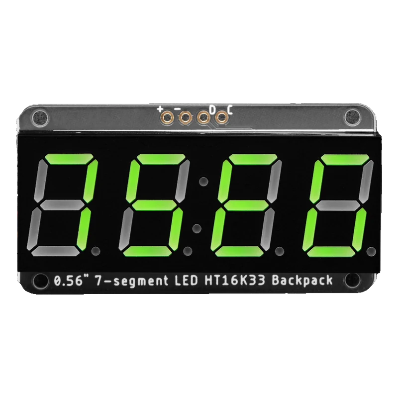
The HT16K33 backpack runs a 0.56-inch 4-digit 7-segment display with a colon from two I2C wires: Holtek's HT16K33 multiplexes up to 16 × 8 LEDs with 16-step dimming and runs I2C at up to 400 kHz (Holtek HT16K33 datasheet Rev. 1.10, pp. 1, 7). It answers at 0x70 by default, up to 0x77 with the A0 to A2 jumpers (Adafruit LED Backpacks guide, Pinouts). Power its + pin at your board's logic voltage, 5 V on an Uno and 3.3 V on an ESP32 or Pico, and drive it with Adafruit's LED Backpack library.
Four 7-segment digits normally need a dozen pins and constant multiplexing. The HT16K33 on the back of this board does the refreshing from its own 16 × 8 bit RAM, sets brightness in 16 steps and can even scan a key matrix (Holtek HT16K33 datasheet Rev. 1.10, p. 1). The microcontroller writes digits over I2C and is free for everything else.
The 4-pin header is printed +, -, D and C: power, ground, I2C data and I2C clock. Three address jumpers (A0, A1, A2) add 1, 2 and 4 to the default 0x70, so up to eight displays share one bus (Adafruit LED Backpacks guide, Pinouts). The STEMMA QT revision adds two Qwiic-compatible connectors for solder-free chaining.
The HT16K33 is specified for 4.5 V to 5.5 V and reads I2C highs from 0.7 × VDD (pp. 1, 6). Adafruit's advice is to power the backpack at your microcontroller's logic voltage: 5 V is best, and 3 V also works for 3 V boards (Adafruit guide, Arduino wiring), with dimmer digits since the chip is then below its rated supply.
HT16K33 7-Segment Backpack pinout
| Pin | Function | Type |
|---|---|---|
| + | Supply (VCC)Your board's logic voltage, 3 V to 5 V | power in |
| - | Ground | power in |
| D | I2C SDA | bidirectional |
| C | I2C SCL | input |
How to wire the HT16K33 7-Segment Backpack
Pin by pin, for the board you have.
| HT16K33 7-Segment Backpack | Arduino Uno | Note |
|---|---|---|
| + | 5V | |
| - | GND | |
| D | A4 (SDA) | |
| C | A5 (SCL) |
| HT16K33 7-Segment Backpack | ESP32 DevKit V1 | Note |
|---|---|---|
| + | 3V3 | |
| - | GND | |
| D | GPIO21 (D21) | |
| C | GPIO22 (D22) |
- Power + from 3V3, as Adafruit advises for 3 V boards, so the I2C lines stay at 3.3 V; the digits are dimmer than at 5 V.
| HT16K33 7-Segment Backpack | Raspberry Pi Pico | Note |
|---|---|---|
| + | 3V3(OUT) | |
| - | GND | |
| D | GP4 | |
| C | GP5 |
- Power + from 3V3(OUT), not VBUS, so SDA and SCL never reach 5 V.
HT16K33 7-Segment Backpack code
Every example here compiles for its board.
// HT16K33 7-Segment Backpack on Arduino Uno: wiring and a free simulation at https://www.tinkered.ai/components/ht16k33-7segment
// Adafruit 0.56" HT16K33 7-segment backpack on an Arduino Uno: D -> A4, C -> A5, address 0x70
// Counts seconds as MM:SS with a blinking colon.
#include <Wire.h>
#include <Adafruit_GFX.h>
#include <Adafruit_LEDBackpack.h>

Adafruit_7segment display;

void setup() {
  Serial.begin(115200);
  if (!display.begin(0x70)) {
    Serial.println(F("HT16K33 not found at 0x70"));
    while (true) {}
  }
  display.setBrightness(8); // 0 to 15
  Serial.println(F("Display ready"));
}

void loop() {
  unsigned long seconds = millis() / 1000;
  int minutes = (seconds / 60) % 100;
  int secs = seconds % 60;
  display.writeDigitNum(0, minutes / 10); // positions 0, 1, 3, 4 are digits; 2 is the colon
  display.writeDigitNum(1, minutes % 10);
  display.writeDigitNum(3, secs / 10);
  display.writeDigitNum(4, secs % 10);
  display.drawColon(seconds % 2 == 0);
  display.writeDisplay();
  static unsigned long last = 0;
  if (seconds != last) {
    last = seconds;
    Serial.print(F("Elapsed: "));
    Serial.print(minutes);
    Serial.print(':');
    if (secs < 10) Serial.print('0');
    Serial.println(secs);
  }
  delay(100);
}
// HT16K33 7-Segment Backpack on ESP32 DevKit V1: wiring and a free simulation at https://www.tinkered.ai/components/ht16k33-7segment
// Adafruit 0.56" HT16K33 7-segment backpack on an ESP32 DevKit V1: D -> GPIO21, C -> GPIO22, address 0x70
// Counts seconds as MM:SS with a blinking colon.
#include <Wire.h>
#include <Adafruit_GFX.h>
#include <Adafruit_LEDBackpack.h>

Adafruit_7segment display;

void setup() {
  Serial.begin(115200);
  Wire.begin(21, 22); // SDA, SCL
  if (!display.begin(0x70, &Wire)) {
    Serial.println("HT16K33 not found at 0x70");
    while (true) { delay(100); }
  }
  display.setBrightness(15); // full brightness helps at 3.3 V
  Serial.println("Display ready");
}

void loop() {
  unsigned long seconds = millis() / 1000;
  int minutes = (seconds / 60) % 100;
  int secs = seconds % 60;
  display.writeDigitNum(0, minutes / 10);
  display.writeDigitNum(1, minutes % 10);
  display.writeDigitNum(3, secs / 10);
  display.writeDigitNum(4, secs % 10);
  display.drawColon(seconds % 2 == 0);
  display.writeDisplay();
  static unsigned long last = 0;
  if (seconds != last) {
    last = seconds;
    Serial.printf("Elapsed: %d:%02d\n", minutes, secs);
  }
  delay(100);
}
// HT16K33 7-Segment Backpack on Raspberry Pi Pico: wiring and a free simulation at https://www.tinkered.ai/components/ht16k33-7segment
// Adafruit 0.56" HT16K33 7-segment backpack on a Raspberry Pi Pico (arduino-pico): D -> GP4, C -> GP5, address 0x70
// Counts seconds as MM:SS with a blinking colon.
#include <Wire.h>
#include <Adafruit_GFX.h>
#include <Adafruit_LEDBackpack.h>

Adafruit_7segment display;

void setup() {
  Serial.begin(115200);
  Wire.setSDA(4);
  Wire.setSCL(5);
  if (!display.begin(0x70, &Wire)) {
    Serial.println("HT16K33 not found at 0x70");
    while (true) { delay(100); }
  }
  display.setBrightness(15);
  Serial.println("Display ready");
}

void loop() {
  unsigned long seconds = millis() / 1000;
  int minutes = (seconds / 60) % 100;
  int secs = seconds % 60;
  display.writeDigitNum(0, minutes / 10);
  display.writeDigitNum(1, minutes % 10);
  display.writeDigitNum(3, secs / 10);
  display.writeDigitNum(4, secs % 10);
  display.drawColon(seconds % 2 == 0);
  display.writeDisplay();
  static unsigned long last = 0;
  if (seconds != last) {
    last = seconds;
    Serial.print("Elapsed: ");
    Serial.print(minutes);
    Serial.print(':');
    if (secs < 10) Serial.print('0');
    Serial.println(secs);
  }
  delay(100);
}
Before you wire it
- Power + at the same voltage as your board's logic (Adafruit LED Backpacks guide): 5 V on an Uno, 3.3 V on an ESP32 or Pico.
- Give each backpack on a shared bus its own address with the A0 to A2 jumpers (0x70 to 0x77).
- Call writeDisplay() after print() or drawColon(); nothing changes on the digits until then.
- Check the display's orientation against the outline printed on the backpack before soldering it.
- Never power + from 5 V while D and C go to a 3.3 V board's pins.
- Never exceed 400 kHz on the bus (Holtek datasheet, p. 7).
- Never mix this up with a TM1637 board: the HT16K33 is a real I2C device with an address, the TM1637 is not.
- The HT16K33 is rated 4.5 V to 5.5 V (Holtek datasheet, p. 1); at 3.3 V it runs as Adafruit describes but the LEDs are dimmer, so raise setBrightness() to 15.
- The chip draws about 1 mA itself (p. 6); nearly all the board's current goes into the lit segments.
- print() right-aligns numbers; writeDigitNum(position, digit) writes a single digit, with position 2 reserved for the colon.
- Several displays and I2C sensors can share the bus as long as every address is different.
- The same library drives Adafruit's 1.2-inch 7-segment, 8 × 8 matrix and alphanumeric backpacks, all built on the HT16K33.
Specifications
- Driver supply
- 4.5 V to 5.5 V (HT16K33 rating)Holtek HT16K33 datasheet Rev. 1.10, p. 1
- Board power
- Same voltage as your board's logic: 5 V best, 3 V also worksAdafruit LED Backpacks guide, 0.56" 7-segment Arduino wiring
- Display capacity
- 16 × 8 bit RAM, up to 128 LEDs; 13 × 3 key scanHoltek HT16K33 datasheet Rev. 1.10, p. 1
- Brightness
- 16-step dimmingHoltek HT16K33 datasheet Rev. 1.10, p. 1
- I2C
- Up to 400 kHz; SDA and SCL high from 0.7 × VDDHoltek HT16K33 datasheet Rev. 1.10, pp. 6 to 7
- I2C address
- 0x70 default; A0, A1, A2 jumpers add 1, 2, 4 (0x70 to 0x77)Adafruit LED Backpacks guide, Pinouts
- Driver current
- 1 mA typical operating, 1 µA typical standby (LED current extra)Holtek HT16K33 datasheet Rev. 1.10, p. 6
- Display
- 0.56-inch, 4 digits with centre colon; red, yellow, green, blue or whiteAdafruit products 878, 879, 880, 881, 1002
From the Adafruit LED Backpacks guide and Holtek HT16K33 datasheet Rev. 1.10, published by Holtek (HT16K33), board by Adafruit.
Common mistakes
Display stays blank
Usually writeDisplay() is missing after print(), or the address is wrong because an A0 to A2 jumper is bridged. Run an I2C scanner: the backpack answers between 0x70 and 0x77 (Adafruit LED Backpacks guide, Pinouts).
5 V on + with a 3.3 V board
Adafruit's backpack expects + at the logic voltage of the board it talks to. With + at 5 V, the I2C lines can sit at 5 V, beyond what an ESP32 or Pico pin accepts.
Digits upside down
The 7-segment display can be soldered on rotated. Match it to the outline printed on the backpack before soldering, because undoing it means desoldering every pin.
Colon in the wrong place
Position 2 of the display is the colon, so the digits are positions 0, 1, 3 and 4. Use writeDigitNum() on those positions, or print() for whole numbers, and drawColon() for the colon.
HT16K33 7-Segment Backpack questions
What is the I2C address of the HT16K33 backpack?
0x70 by default. Bridging A0, A1 or A2 adds 1, 2 or 4, so addresses run from 0x70 to 0x77 and eight backpacks can share a bus (Adafruit LED Backpacks guide, Pinouts).
Does the HT16K33 backpack work with an ESP32 or Pico at 3.3 V?
Yes. Adafruit says to power it at the board's logic voltage and that 3 V works for 3 V boards. The HT16K33 is rated 4.5 V to 5.5 V (Holtek datasheet, p. 1), so at 3.3 V the digits are dimmer.
Which library drives it?
Adafruit LED Backpack Library with Adafruit GFX. Adafruit_7segment provides print(), drawColon(), writeDigitNum() and setBrightness().
HT16K33 or TM1637 display?
Both run 4-digit 7-segment displays. The HT16K33 is a standard I2C device with eight selectable addresses that shares the bus with sensors; the TM1637 uses its own two-wire protocol on any two pins.
How do I set the brightness?
Call setBrightness(0) to setBrightness(15); the HT16K33 has 16 dimming steps (Holtek datasheet, p. 1).
Build something with the HT16K33 7-Segment Backpack
- Build this
I2C desk clock
Hours and minutes with a blinking colon from a DS3231.
- Build this
Workout interval timer
Count down work and rest periods with a buzzer at each change.
This page as plain Markdown, for ChatGPT, Claude or your own agent. /components/ht16k33-7segment.md