DIP Switch (4 positions)
Four independent on/off slide switches in a breadboard-friendly DIP package, read by a microcontroller as a 4-bit setting.
- Circuit4 independent SPST switches (one pole per position)
- Pin pitch2.54 mm between pins, 7.62 mm between rows
- Switching rating50 mA at 24 VDC (10,000-cycle actuation life)
- Non-switching rating100 mA or 50 VDC
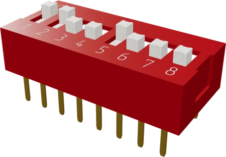
A 4-position DIP switch is four independent SPST slide switches in a through-hole package on a 2.54 mm pitch with 7.62 mm between its two rows, so it straddles a breadboard's centre channel (CTS Series 206 datasheet, p. 3). Wire one side of each switch to its own GPIO set to INPUT_PULLUP and the other side to GND: a switch turned ON then reads LOW. It is a signal-level part, rated for 50 mA at 24 VDC switching and 100 mA or 50 VDC non-switching (p. 2), so never run a load through it.
A DIP (dual in-line package) switch packs several tiny slide switches into the same footprint as a chip. This 4-position version holds four single-pole, single-throw (SPST) switches, each an independent contact between a pin on one row and the pin opposite it on the other row. Nothing is shared between positions, so each switch needs its own GPIO and its own path to ground. The kit part is Connfly's DS1040 series; the figures here come from CTS's Series 206, the reference through-hole DIP switch of this type.
The pins sit on a 2.54 mm pitch with the two rows 7.62 mm apart, the same 300 mil spacing as a DIP-8 chip, and the slider travels 2.03 mm (CTS Series 206 datasheet, p. 3). On most switches an ON marking on the housing shows which way closes the contact; on the CTS part ON is toward the dot (p. 3).
DIP switches are configuration devices: set once and read at power-up to choose an address, a mode or an option. CTS rates the Series 206 at 50 mA and 24 VDC for its 10,000-cycle switching life test, and 100 mA or 50 VDC when carrying current without switching it (p. 2). Contact resistance starts at 50 mΩ or less (p. 2), which is irrelevant for a logic input with a pull-up but rules out power loads.
DIP Switch (4 positions) pinout
| Pin | Function | Type |
|---|---|---|
| 1A | SW1 side A | passive |
| 2A | SW2 side A | passive |
| 3A | SW3 side A | passive |
| 4A | SW4 side A | passive |
| 1B | SW1 side B | passive |
| 2B | SW2 side B | passive |
| 3B | SW3 side B | passive |
| 4B | SW4 side B | passive |
How to wire the DIP Switch (4 positions)
Pin by pin, for the board you have.
| DIP Switch (4 positions) | Arduino Uno | Note |
|---|---|---|
| 1A | D2 | |
| 2A | D3 | |
| 3A | D4 | |
| 4A | D5 | |
| 1B | GND | |
| 2B | GND | |
| 3B | GND | |
| 4B | GND |
| DIP Switch (4 positions) | ESP32 DevKit V1 | Note |
|---|---|---|
| 1A | GPIO13 (D13) | |
| 2A | GPIO14 (D14) | |
| 3A | GPIO27 (D27) | |
| 4A | GPIO26 (D26) | |
| 1B | GND | |
| 2B | GND | |
| 3B | GND | |
| 4B | GND |
| DIP Switch (4 positions) | Raspberry Pi Pico | Note |
|---|---|---|
| 1A | GP0 | |
| 2A | GP1 | |
| 3A | GP2 | |
| 4A | GP3 | |
| 1B | GND | |
| 2B | GND | |
| 3B | GND | |
| 4B | GND |
Before you wire it
- GPIO wiring: one side to GND, other side to the GPIO with INPUT_PULLUP → closed/ON reads LOW. This inversion is the #1 DIP-switch confusion: document it in the firmware. SPDT alternative: common → GPIO, throws to GND and 3V3 = defined level in both positions, no pull needed.
- DIP banks: each position to its own GPIO (pull-ups on), commons ganged to GND. Read once at boot for configuration; no debounce needed for a boot-time read.
- Small slide (SS12D class): ~0.3 A low-voltage DC
- Mini toggle (MTS-102 class): 6 A/125 VAC, 3 A/250 VAC
- Debounce when counting EDGES: real switches chatter ~1.6 ms on average, 6 ms worst (Ganssle's measurements), a 20–50 ms window still feels instantaneous. Level reads don't need it.
- Keep it to 50 mA at 24 VDC switching (100 mA at 50 VDC carrying, 10,000 cycles, CTS 206)
- No mains (120/230 VAC) through hobby slide/DIP/tact switches: no arc extinction margin in DC, no creepage, no agency approval. Mains needs a properly AC-rated approved switch or a relay.
- No floating input: a switch to GND without the pull-up enabled reads noise.
- No leaving both throws of an SPDT unwired while COM drives a GPIO: the input then floats in one position. Wire both throws to levels, or use INPUT_PULLUP with one throw to GND.
- Wire each switch between its own GPIO and GND, and enable the internal pull-up with pinMode(pin, INPUT_PULLUP). A closed (ON) switch then reads LOW and an open one reads HIGH, so invert the reading in code if you want 1 to mean ON.
- Each position is isolated from the others. Every switch needs a ground connection on its own pin; tie all four ground-side pins to the GND rail.
- Plug it across the breadboard's centre channel like a DIP chip: the 7.62 mm row spacing (CTS Series 206 datasheet, p. 3) puts each switch's two pins on opposite sides of the gap.
- Read DIP switches once in setup() for configuration; a level read at boot needs no debouncing. Debounce only if you react to the switch changing while the sketch runs.
- Keep the current small. The switching rating is 50 mA at 24 VDC (datasheet, p. 2): drive LEDs, relays or motors through a transistor or MOSFET that the switch's GPIO reading controls, never through the switch itself.
DIP Switch (4 positions) variants
The same part in the values and versions the studio carries.
| Variant | Positions |
|---|---|
| DIP Switch (1 position) | 1 |
| DIP Switch (2 positions) | 2 |
| DIP Switch (3 positions) | 3 |
| DIP Switch (4 positions) | 4 |
| DIP Switch (5 positions) | 5 |
| DIP Switch (6 positions) | 6 |
| DIP Switch (7 positions) | 7 |
| DIP Switch (8 positions) | 8 |
| DIP Switch (9 positions) | 9 |
| DIP Switch (10 positions) | 10 |
| DIP Switch (11 positions) | 11 |
| DIP Switch (12 positions) | 12 |
Specifications
- Circuit
- 4 independent SPST switches (one pole per position)CTS Series 206 datasheet Rev. G, pp. 1, 3
- Pin pitch
- 2.54 mm between pins, 7.62 mm between rowsCTS Series 206 datasheet Rev. G, p. 3
- Switching rating
- 50 mA at 24 VDC (10,000-cycle actuation life)CTS Series 206 datasheet Rev. G, p. 2
- Non-switching rating
- 100 mA or 50 VDCCTS Series 206 datasheet Rev. G, p. 2
- Contact resistance
- 50 mΩ max initial, 100 mΩ max at end of lifeCTS Series 206 datasheet Rev. G, p. 2
- Insulation resistance
- 1000 MΩ min between insulated terminalsCTS Series 206 datasheet Rev. G, p. 2
- Slide travel
- 2.03 mmCTS Series 206 datasheet Rev. G, p. 3
- Operating temperature
- -55 °C to +85 °CCTS Series 206 datasheet Rev. G, p. 2
- Dimensions
- 11.62 × 9.9 × 6.8 mm
- Contact rating
- 50 mA at 24 VDC switching, 100 mA at 50 VDC carrymaker's datasheet, checked 29 Oct 2026
- Life
- 10,000 cyclesmaker's datasheet, checked 29 Oct 2026
Common mistakes
Forgetting the pull-up
With one side on GND and no pull-up, an open switch leaves the input floating, and it reads random values. Use INPUT_PULLUP, or add a 10 kΩ resistor from the GPIO to the supply.
Reading ON as HIGH
With the pull-up wiring, ON connects the pin to ground and reads LOW. Code that expects HIGH for ON shows every setting inverted. Invert the bits when you build the value.
Wiring the switches as if they shared a common
The four positions are independent contacts, not a common pin with four outputs. Connecting only one ground pin leaves the other three switches with nothing to close against.
Switching a load through it
DIP switches are rated for signal currents: 50 mA at 24 VDC switching on the CTS Series 206 (datasheet, p. 2). Motors, LED strips and mains wiring weld or burn the contacts. Switch loads with a transistor, MOSFET or relay.
Placing it along a breadboard row
Pushed into one side of the board, both pins of each switch land in the same connected strip and the switch is shorted out. Straddle the centre channel so each row of pins sits in its own strips.
DIP Switch (4 positions) questions
How do I wire a 4-position DIP switch to an Arduino?
Put the switch across the breadboard's centre channel, wire one pin of each position to its own digital pin (for example D2 to D5) and the opposite pin to GND, then set each pin to INPUT_PULLUP. A switch turned ON reads LOW. The 2.54 mm pitch and 7.62 mm row spacing make it fit like a DIP chip (CTS Series 206 datasheet, p. 3).
Does a DIP switch work with a 3.3 V board like the ESP32?
Yes. The switch is a passive contact, so it works at any logic voltage well inside its 24 VDC switching rating (CTS Series 206 datasheet, p. 2). Use the ESP32's internal pull-ups on pins that have them, and avoid GPIO34 to 39, which have no internal pull-up resistors.
Why does my DIP switch read the opposite of what I set?
With INPUT_PULLUP wiring, an ON switch connects the pin to ground, so it reads LOW (0). That is expected: invert each bit in code, for example value |= (digitalRead(pin) == LOW) << i.
How do I read a 4-position DIP switch as a number?
Read the four pins in order and set one bit per switch, position 1 as the least significant bit. Four switches give 16 combinations, 0 to 15, which is handy for a device address or a mode number read once at power-up.
How much current can a DIP switch handle?
Very little. CTS rates its Series 206 at 50 mA and 24 VDC while switching and 100 mA or 50 VDC while carrying current without switching (datasheet, p. 2). Treat it as a logic input, not a power switch.
What is the difference between a DIP switch and a slide switch?
A DIP switch is several tiny SPST switches in one chip-sized package, set occasionally with a pen tip or fingernail. A slide switch is usually a single SPDT switch with a common pin and two throws, sized for a finger, and often used as a power or mode switch.
Build something with the DIP Switch (4 positions)
- Build this
Device address selector
Give each node in an RS-485, I2C or radio network a unique ID by reading four switches at boot.
- Build this
Mode or configuration select
Choose between operating modes, baud rates or test settings without reflashing the firmware.
- Build this
Binary counter teaching aid
Set a 4-bit number by hand and show it in decimal on a 7-segment display or the serial monitor.
- Build this
Feature toggles for a build
Turn options such as sound, logging or debug output on and off on a finished project.
This page as plain Markdown, for ChatGPT, Claude or your own agent. /components/dip-switch-4.md