ADXL345
An Analog Devices 3-axis digital accelerometer breakout with ±2 g to ±16 g ranges, read over I2C or SPI, for tilt, motion, tap and free-fall detection.
- Chip supplyVS 2.0 V to 3.6 V (2.5 V typical); VDD I/O 1.7 V to VS
- Absolute maximum-0.3 V to 3.6 V on VS and VDD I/O; 10,000 g shock, powered or not
- Ranges and resolution±2, ±4, ±8, ±16 g; 10-bit, or up to 13-bit full resolution at about 4 mg/LSB (3.9 mg typical)
- Output data rate6.25 Hz to 3200 Hz
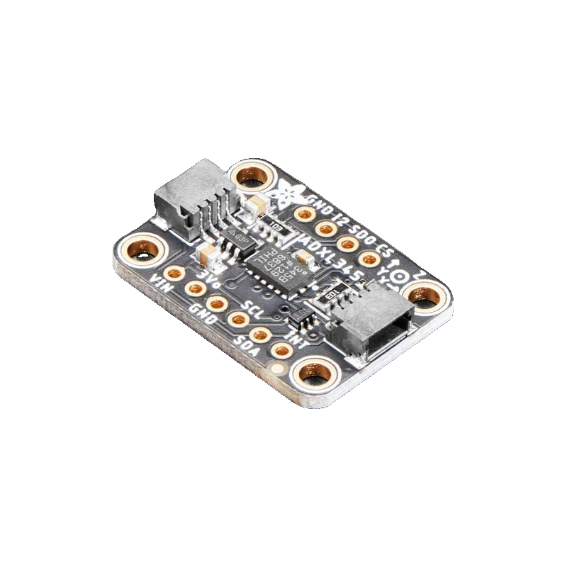
The ADXL345 is a 3-axis accelerometer with selectable ±2, ±4, ±8 or ±16 g ranges and up to 13-bit resolution at a constant 4 mg/LSB (3.9 mg typical), output from 6.25 Hz to 3200 Hz (Analog Devices ADXL345 datasheet Rev. 0, pp. 1, 3). Over I2C it answers at 0x53 with SDO low or 0x1D with SDO high (p. 10). The chip itself is a 2.0 V to 3.6 V part (p. 3); the Adafruit breakout adds a 3.3 V regulator and I2C level shifting, so VIN takes 3.3 V or 5 V.
The ADXL345 measures static acceleration (gravity, so tilt) and dynamic acceleration (motion, shock) on three axes. In full resolution mode the scale stays at about 4 mg per count whatever the range, using up to 13 bits at ±16 g (ADI datasheet Rev. 0, pp. 1, 3). Built-in detectors for single and double tap, activity, inactivity and free fall can raise its INT1 or INT2 pins without the microcontroller polling.
It is frugal: 40 µA below 10 Hz, 145 µA above 100 Hz, and 0.1 µA in standby at 2.5 V (p. 3). The chip runs from 2.0 V to 3.6 V with a separate I/O supply (p. 3) and survives 10,000 g of shock (p. 4).
The Adafruit breakout puts a 3.3 V regulator on VIN and level shifts SDA and SCL, so it works with 3.3 V and 5 V boards over I2C (Adafruit ADXL345 guide, pp. 9 to 11). Its CS pin idles high to select I2C and SDO is pulled low for address 0x53. The guide notes that SPI is not level shifted on all pins, so use I2C with a 5 V board.
ADXL345 pinout
| Pin | Function | Type |
|---|---|---|
| VIN | VIN3.3 V to 5 V | power in |
| 3Vo | 3Vo3.3 V | power out |
| GND | GND | power in |
| SCL | I2C SCL, SPI SCKLevel shifted to VIN for I2C | input |
| SDA | I2C SDA, SPI MOSILevel shifted to VIN for I2C | bidirectional |
| CS | SPI CS, Mode select | input |
| SDO | SPI MISO, I2C address select3.3 V | bidirectional |
| INT1 | Interrupt3.3 V | output |
| INT2 | Interrupt3.3 V | output |
How to wire the ADXL345
Pin by pin, for the board you have.
| ADXL345 | Arduino Uno | Note |
|---|---|---|
| VIN | 5V | |
| GND | GND | |
| SCL | A5 | |
| SDA | A4 |
- The bare GY-291 board often has no level shifter and only a 3.3 V regulator, if any: on an Uno, power it from 3.3V and keep the bus at 3.3 V, since the chip's absolute maximum is 3.6 V (ADI datasheet, p. 4).
| ADXL345 | ESP32 DevKit V1 | Note |
|---|---|---|
| VIN | 3V3 | |
| GND | GND | |
| SCL | GPIO22 (D22) | |
| SDA | GPIO21 (D21) |
- Power VIN from 3V3 so the level-shifted I2C lines sit at 3.3 V.
| ADXL345 | Raspberry Pi Pico | Note |
|---|---|---|
| VIN | 3V3(OUT) | |
| GND | GND | |
| SCL | GP5 | |
| SDA | GP4 |
- Power VIN from 3V3(OUT), not VBUS, so the I2C lines never reach 5 V.
ADXL345 code
Every example here compiles for its board.
// ADXL345 on Arduino Uno: wiring and a free simulation at https://www.tinkered.ai/components/adxl345
// ADXL345 on an Arduino Uno: VIN 5V, SDA A4, SCL A5, address 0x53
#include <Wire.h>
#include <Adafruit_Sensor.h>
#include <Adafruit_ADXL345_U.h>

Adafruit_ADXL345_Unified accel(12345);

void setup() {
  Serial.begin(115200);
  Wire.begin();
  if (!accel.begin(0x53)) {
    Serial.println("ADXL345 not found at 0x53. Check wiring and SDO.");
    while (true) delay(10);
  }
  accel.setRange(ADXL345_RANGE_4_G);
  accel.setDataRate(ADXL345_DATARATE_100_HZ);
  Serial.println("ADXL345 ready, range +/-4 g");
}

void loop() {
  sensors_event_t event;
  accel.getEvent(&event);  // m/s^2; 9.81 m/s^2 is 1 g
  Serial.print("X: ");
  Serial.print(event.acceleration.x, 2);
  Serial.print("  Y: ");
  Serial.print(event.acceleration.y, 2);
  Serial.print("  Z: ");
  Serial.print(event.acceleration.z, 2);
  Serial.println("  m/s^2");
  delay(200);
}
// ADXL345 on ESP32 DevKit V1: wiring and a free simulation at https://www.tinkered.ai/components/adxl345
// ADXL345 on an ESP32 DevKit V1: VIN 3V3, SDA GPIO21, SCL GPIO22, address 0x53
#include <Wire.h>
#include <Adafruit_Sensor.h>
#include <Adafruit_ADXL345_U.h>

Adafruit_ADXL345_Unified accel(12345);

void setup() {
  Serial.begin(115200);
  Wire.begin(21, 22);  // SDA, SCL
  if (!accel.begin(0x53)) {
    Serial.println("ADXL345 not found at 0x53. Check wiring and SDO.");
    while (true) delay(10);
  }
  accel.setRange(ADXL345_RANGE_4_G);
  accel.setDataRate(ADXL345_DATARATE_100_HZ);
  Serial.println("ADXL345 ready, range +/-4 g");
}

void loop() {
  sensors_event_t event;
  accel.getEvent(&event);  // m/s^2; 9.81 m/s^2 is 1 g
  Serial.print("X: ");
  Serial.print(event.acceleration.x, 2);
  Serial.print("  Y: ");
  Serial.print(event.acceleration.y, 2);
  Serial.print("  Z: ");
  Serial.print(event.acceleration.z, 2);
  Serial.println("  m/s^2");
  delay(200);
}
// ADXL345 on Raspberry Pi Pico: wiring and a free simulation at https://www.tinkered.ai/components/adxl345
// ADXL345 on a Raspberry Pi Pico (arduino-pico): VIN 3V3(OUT), SDA GP4, SCL GP5, address 0x53
#include <Wire.h>
#include <Adafruit_Sensor.h>
#include <Adafruit_ADXL345_U.h>

Adafruit_ADXL345_Unified accel(12345);

void setup() {
  Serial.begin(115200);
  Wire.setSDA(4);
  Wire.setSCL(5);
  Wire.begin();
  if (!accel.begin(0x53)) {
    Serial.println("ADXL345 not found at 0x53. Check wiring and SDO.");
    while (true) delay(10);
  }
  accel.setRange(ADXL345_RANGE_4_G);
  accel.setDataRate(ADXL345_DATARATE_100_HZ);
  Serial.println("ADXL345 ready, range +/-4 g");
}

void loop() {
  sensors_event_t event;
  accel.getEvent(&event);  // m/s^2; 9.81 m/s^2 is 1 g
  Serial.print("X: ");
  Serial.print(event.acceleration.x, 2);
  Serial.print("  Y: ");
  Serial.print(event.acceleration.y, 2);
  Serial.print("  Z: ");
  Serial.print(event.acceleration.z, 2);
  Serial.println("  m/s^2");
  delay(200);
}
Before you wire it
- Keep CS high at power-up for I2C; the chip enters SPI mode if CS is low at reset (Adafruit guide, p. 11).
- Set SDO before power-up: low for 0x53, high for 0x1D (datasheet, p. 10). Two sensors on one bus need one of each.
- Choose the smallest range that covers the motion: ±2 g for tilt, ±16 g for impacts, with full resolution keeping about 4 mg/LSB (pp. 1, 3).
- Bolt the board rigidly to what it measures; a loose board adds its own vibration.
- Never put more than 3.6 V on a board that has no regulator, the chip's absolute maximum (datasheet, p. 4).
- Never run SPI from a 5 V board through the Adafruit breakout: only the I2C lines are level shifted (guide, p. 11).
- Never expect a heading from it: an accelerometer gives tilt from gravity, not rotation about the vertical axis.
- The interrupt pins INT1 and INT2 can carry tap, double tap, activity, inactivity and free-fall events, mapped by register; they output at the chip's 3.3 V level.
- Tilt is atan2 of the gravity components: pitch = atan2(-x, sqrt(y*y + z*z)) and roll = atan2(y, z), valid while the board is not accelerating.
- Current rises with data rate, from 40 µA below 10 Hz to 145 µA above 100 Hz (datasheet, p. 3); pick 100 Hz or less for battery projects.
- Each axis has a factory offset; for precise tilt, record the reading on a level surface and subtract it, or write the OFSX, OFSY and OFSZ registers.
Specifications
- Chip supply
- VS 2.0 V to 3.6 V (2.5 V typical); VDD I/O 1.7 V to VSAnalog Devices ADXL345 datasheet Rev. 0, p. 3
- Absolute maximum
- -0.3 V to 3.6 V on VS and VDD I/O; 10,000 g shock, powered or notAnalog Devices ADXL345 datasheet Rev. 0, p. 4
- Ranges and resolution
- ±2, ±4, ±8, ±16 g; 10-bit, or up to 13-bit full resolution at about 4 mg/LSB (3.9 mg typical)Analog Devices ADXL345 datasheet Rev. 0, pp. 1, 3
- Output data rate
- 6.25 Hz to 3200 HzAnalog Devices ADXL345 datasheet Rev. 0, p. 3
- I2C address
- 0x53 (SDO/ALT ADDRESS low) or 0x1D (high); 100 kHz and 400 kHzAnalog Devices ADXL345 datasheet Rev. 0, p. 10
- SPI
- 3- or 4-wire, up to 5 MHzAnalog Devices ADXL345 datasheet Rev. 0, p. 8
- Device ID
- 0xE5 in register 0x00Analog Devices ADXL345 datasheet Rev. 0, p. 15
- Supply current
- 40 µA below 10 Hz, 145 µA above 100 Hz, 0.1 µA standby (VS = 2.5 V)Analog Devices ADXL345 datasheet Rev. 0, p. 3
- Breakout
- 3.3 V regulator (3Vo out, under 100 mA) and I2C level shifting; SDO pulled low (0x53), CS high selects I2CAdafruit ADXL345 guide (PDF), pp. 9 to 11
From the ADXL345 product page and datasheet, published by Analog Devices.
Common mistakes
Scanning finds 0x1D instead of 0x53
SDO floats or sits high on some clone boards. The datasheet gives 0x53 for SDO low and 0x1D for SDO high (p. 10). Tie SDO to GND or call begin(0x1D).
Readings stuck at zero
The ADXL345 powers up in standby. A library's begin() sets the measure bit; a hand-written driver must write 0x08 to POWER_CTL (0x2D) before data appears.
Feeding a 3.3 V-only clone 5 V
Many GY-291 boards have no level shifter. 5 V on their SDA and SCL exceeds the chip's 3.6 V absolute maximum (p. 4). Check the board before wiring it to an Uno's 5 V bus.
Noisy tilt angles
Vibration shows up directly in the angle. Lower the data rate, average a few samples, or use a gyro-equipped IMU for moving platforms.
ADXL345 questions
What is the ADXL345's I2C address?
0x53 with SDO/ALT ADDRESS tied low and 0x1D with it high (ADI datasheet Rev. 0, p. 10). The Adafruit breakout pulls SDO low, so it answers at 0x53.
Is the ADXL345 5 V tolerant?
The chip is not: its supply and pins are rated to 3.6 V absolute maximum (p. 4). The Adafruit breakout's regulator and I2C level shifter make it safe on a 5 V Uno; bare GY-291 boards may not be.
ADXL345 or MPU6050?
The ADXL345 is an accelerometer only, with built-in tap and free-fall detection and microamp current. The MPU6050 adds a gyroscope, which you need to track rotation on a moving object.
What resolution does it really have?
In full resolution mode about 4 mg per count on every range (3.9 mg typical at ±2 g), using 10 bits at ±2 g and up to 13 bits at ±16 g (datasheet, pp. 1, 3).
Can it detect a fall?
Yes. The free-fall detector watches for all axes near 0 g for a set time and can raise INT1 or INT2, so a microcontroller can sleep until it happens.
Build something with the ADXL345
- Build this
Digital spirit level
Show pitch and roll in degrees on an OLED.
- Build this
Knock to unlock
Use the double-tap interrupt as a secret knock.
- Build this
Vibration logger
Record peak g on a washing machine or a 3D printer.
This page as plain Markdown, for ChatGPT, Claude or your own agent. /components/adxl345.md