ADS1115 16-Bit ADC with an ESP32 DevKit V1
A 16-bit, four-input I2C analog-to-digital converter with a programmable gain amplifier, from ±0.256 V to ±6.144 V full scale.
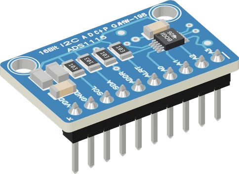
The ADS1115 is the usual fix for the ESP32's own ADC: on an ESP32 DevKit V1 it sits on the default I2C pins, SDA on GPIO21 and SCL on GPIO22, powered from 3V3. Its 16-bit result arrives over I2C, so it keeps reading while Wi-Fi runs, which ADC2 pins on the ESP32 cannot.
Wiring the ADS1115 16-Bit ADC to the ESP32 DevKit V1
Pin by pin.
| ADS1115 16-Bit ADC | ESP32 DevKit V1 |
|---|---|
| VDD | 3V3 |
| GND | GND |
| SDA | GPIO21 (D21) |
| SCL | GPIO22 (D22) |
What to know on the ESP32 DevKit V1
- The ESP32's internal ADC is specified at up to ±12 LSB of integral nonlinearity on 12 bits, measured with Wi-Fi and Bluetooth off; the ADS1115 gives 1 LSB INL at 16 bits. That is the reason to add it to an ESP32 for soil, battery or bridge measurements.Espressif ESP32 Series Datasheet v5.3, p. 43; TI ADS111x datasheet SBAS444E, p. 5
- ADC2 is shared with the Wi-Fi driver, and the ESP32's ADC1 has only the pins GPIO32 to GPIO39. Four ADS1115 inputs on the I2C bus add analog channels without touching either limit.ESP-IDF Programming Guide, ADC Oneshot Mode Driver; Espressif ESP32 Series Datasheet v5.3, p. 46
- With VDD on 3V3 every input must stay between GND - 0.3 V and VDD + 0.3 V, whatever the gain: the GAIN_TWOTHIRDS range in the sketch (±6.144 V) does not let the module read a 5 V signal. Scale higher voltages down with a divider first.TI ADS111x datasheet SBAS444E, pp. 4, 15
- The module's 10 kOhm pull-ups go to its VDD, so keeping VDD on 3V3 holds SDA and SCL at 3.3 V, within the ESP32's VDD + 0.3 V input limit.Espressif ESP32 Series Datasheet v5.3, p. 52
ADS1115 16-Bit ADC code for the ESP32 DevKit V1
Compiled for esp32:esp32:esp32 on 2026-10-30.
// ADS1115 16-Bit ADC on ESP32 DevKit V1: wiring and a free simulation at https://www.tinkered.ai/components/ads1115-adc/esp32
#include <Arduino.h>
#include <Wire.h>
#include <Adafruit_ADS1X15.h>

Adafruit_ADS1115 ads;

void setup() {
  Serial.begin(115200);
  if (!ads.begin(0x48)) {
    Serial.println("ADS1115 not found: check VDD, SDA/SCL and the ADDR wiring");
    while (true) delay(10);
  }
  ads.setGain(GAIN_TWOTHIRDS);
}

void loop() {
  int16_t pot = ads.readADC_SingleEnded(0);
  int16_t tmp = ads.readADC_SingleEnded(1);
  float potV = ads.computeVolts(pot);
  float tempC = (ads.computeVolts(tmp) - 0.5f) * 100.0f;   // TMP36: 0.5 V at 0 °C, 10 mV/°C
  Serial.print("pot "); Serial.print(potV, 4); Serial.print(" V  ");
  Serial.print("temp "); Serial.print(tempC, 2); Serial.println(" C");
  delay(500);
}
ADS1115 16-Bit ADC on the ESP32 DevKit V1: questions
Why use an ADS1115 when the ESP32 already has an ADC?
The ESP32's ADC is 12-bit with up to ±12 LSB INL (ESP32 datasheet, p. 43) and ADC2 stops working while Wi-Fi runs. The ADS1115 is 16-bit, 1 LSB INL (TI datasheet, p. 5), and talks I2C, so Wi-Fi has no effect on it.
Which gain should I use on a 3.3 V ESP32 setup?
GAIN_ONE (±4.096 V) covers a 0 to 3.3 V signal on a 3.3 V supply (TI datasheet, p. 15). The sketch's GAIN_TWOTHIRDS works too, with a coarser 187.5 µV step.
Can I put four ADS1115 boards on one ESP32?
Yes, at 0x48, 0x49, 0x4A and 0x4B by wiring ADDR to GND, VDD, SDA or SCL (TI datasheet, p. 20). The ESP32's second I2C controller is there if you need another bus.
Keep going
This guide as plain Markdown. /components/ads1115-adc/esp32.md