74HC595 Shift Register with a Raspberry Pi Pico
The 74HC595 is an 8-bit serial-in, parallel-out shift register that turns three microcontroller pins into eight latched outputs.
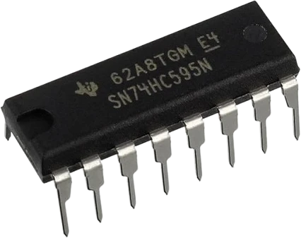
On the Raspberry Pi Pico the 74HC595 runs from 3V3 with SRCLR tied to the same pin, so the RP2040's 3.3 V outputs meet the chip's thresholds and QA to QH never rise above what the Pico itself uses. SER, SRCLK and RCLK go to GP0, GP1 and GP2, and the sketch walks a single lit bit from QA to QH with shiftOut().
Wiring the 74HC595 Shift Register to the Raspberry Pi Pico
Pin by pin.
| 74HC595 Shift Register | Raspberry Pi Pico |
|---|---|
| VCC | 3V3 |
| GND | GND |
| SER | GP0 |
| SRCLK | GP1 |
| RCLK | GP2 |
| SRCLR | 3V3 |
| OE | GND |
What to know on the Raspberry Pi Pico
- The RP2040 guarantees only 2.62 V for a high output at 3.3 V IOVDD, below the 3.15 V a 74HC595 on 5 V requires with a 4.5 V supply. Powered from 3V3, the chip's threshold falls to about 0.7 x 3.3 V, near 2.3 V, which the Pico's outputs clear.RP2040 datasheet, section 5.5.3.4, Table 625; TI SN74HC595 datasheet SCLS041J, p. 4
- Raspberry Pi suggests keeping external loads on the Pico's 3V3 pin under 300 mA. For LEDs on QA to QH the tighter bound is the chip's own 70 mA through VCC or GND, and its 80 µA idle draw is negligible.Raspberry Pi Pico datasheet, release 21, p. 8; TI SN74HC595 datasheet SCLS041J, pp. 1, 4
- GP0 and GP1 are where arduino-pico puts Serial1 (UART0 TX and RX) by default. This sketch opens no UART, so they are free; a project that needs Serial1 should move SER and SRCLK or give Serial1 other pins with setTX() and setRX() before begin().arduino-pico variants/rpipico/pins_arduino.h; RP2040 datasheet, section 2.19.2, Table 279
- For hardware SPI, wire SER to GP19 (SPI0 TX) and SRCLK to GP18 (SPI0 SCK), the pins arduino-pico's SPI object uses by default, then latch with RCLK after SPI.transfer(). Hold the SPI clock to 5 MHz at most, the frequency TI guarantees at its lowest 2 V supply.arduino-pico variants/rpipico/pins_arduino.h; TI SN74HC595 datasheet SCLS041J, p. 6
74HC595 Shift Register code for the Raspberry Pi Pico
Compiled for rp2040:rp2040:rpipico on 2026-10-29.
// 74HC595 Shift Register on Raspberry Pi Pico: wiring and a free simulation at https://www.tinkered.ai/components/74hc595-shift-register/raspberry-pi-pico
const int DATA_PIN  = 0;   // SER   (DS)
const int CLOCK_PIN = 1;   // SRCLK (SH_CP)
const int LATCH_PIN = 2;   // RCLK  (ST_CP)

void setup() {
  pinMode(DATA_PIN, OUTPUT);
  pinMode(CLOCK_PIN, OUTPUT);
  pinMode(LATCH_PIN, OUTPUT);
}

// MSBFIRST: bit 7 -> QH, bit 0 -> QA.
void writeByte(byte value) {
  digitalWrite(LATCH_PIN, LOW);
  shiftOut(DATA_PIN, CLOCK_PIN, MSBFIRST, value);
  digitalWrite(LATCH_PIN, HIGH);   // RCLK rising latches to QA..QH
}

void loop() {
  for (int i = 0; i < 8; i++) {    // walking 1: QA -> QH
    writeByte(1 << i);
    delay(150);
  }
}
74HC595 Shift Register on the Raspberry Pi Pico: questions
Can I power the 74HC595 from the Pico's VBUS pin?
Not while GP0 to GP2 drive it. On VBUS, about 5 V from USB, the chip needs 3.15 V or more for a high at a 4.5 V supply (TI, p. 4), and the RP2040 only guarantees 2.62 V (RP2040 datasheet, Table 625). The page wires VCC and SRCLR to 3V3 for that reason.
Do I need a level shifter between the Pico and the 74HC595?
No. With the chip on the Pico's 3V3 rail, every signal in both directions swings between the same GND and 3.3 V, so QA to QH can also feed other 3.3 V logic directly.
Why do the 74HC595 outputs stay dark on my Pico?
Check the two control pins first: OE must sit at GND to enable QA to QH, and SRCLR must sit at 3V3 or the register keeps clearing (TI datasheet, p. 3). Then check RCLK on GP2, since the outputs only change on its rising edge.
Keep going
This guide as plain Markdown. /components/74hc595-shift-register/raspberry-pi-pico.md