74HC165 Shift Register with an ESP32 DevKit V1
The 74HC165 is an 8-bit parallel-in, serial-out shift register that reads eight buttons or switches on three microcontroller pins.
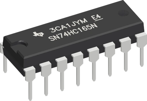
On the ESP32 DevKit V1 the 74HC165 runs from the 3V3 pin, so QH never rises above the 3.3 V that GPIO27 can take. The sketch loads on GPIO13, clocks on GPIO14 and reads QH on GPIO27, three pins that are not among the ESP32's five strapping pins, so the buttons cannot change how the board boots.
Wiring the 74HC165 Shift Register to the ESP32 DevKit V1
Pin by pin.
| 74HC165 Shift Register | ESP32 DevKit V1 | Note |
|---|---|---|
| VCC | 3V3 | |
| GND | GND | |
| SH_LD | GPIO13 (D13) | |
| CLK | GPIO14 (D14) | |
| QH | GPIO27 (D27) | |
| CLK_INH | GND | |
| SER | GND | |
| A | GND | through a 10 kΩ resistor |
| B | GND | through a 10 kΩ resistor |
| C | GND | |
| D | GND | |
| E | GND | |
| F | GND | |
| G | GND | |
| H | GND |
What to know on the ESP32 DevKit V1
- Keep VCC on 3V3. The chip runs from 2 V to 6 V and QH swings to its own VCC, while an ESP32 input is rated to VDD + 0.3 V at most; a 74HC165 on VIN would put about 5 V on GPIO27.TI SN74HC165 datasheet SCLS116H, p. 4; Espressif ESP32 Series Datasheet v5.3, p. 52
- The pins avoid GPIO0, GPIO2, GPIO5, GPIO12 and GPIO15, which the ESP32 samples at reset. That matters here because the inputs A to H are buttons: a register line on GPIO12 or GPIO0 held at the wrong level during reset would change the boot mode or the flash voltage.Espressif ESP32 Series Datasheet v5.3, p. 22; Espressif ESP32-WROOM-32 Datasheet v3.8, p. 13
- Do not move QH to GPIO34 to GPIO39 if you need a pull: those pins are input-only with no internal pull-up or pull-down. QH is a push-pull output, so it reads fine there, but SH_LD and CLK must stay on output-capable pins.Espressif ESP32 Series Datasheet v5.3, p. 61
- For faster reads, the ESP32's VSPI pins work as a hardware path: CLK on GPIO18 (SCK) and QH on GPIO19 (MISO), then one SPI.transfer(0) per register after the load pulse.Espressif ESP32 Series Datasheet v5.3, p. 36
74HC165 Shift Register code for the ESP32 DevKit V1
Compiled for esp32:esp32:esp32 on 2026-10-29.
// 74HC165 Shift Register on ESP32 DevKit V1: wiring and a free simulation at https://www.tinkered.ai/components/74hc165-shift-register/esp32
#include <Arduino.h>

const int LOAD_PIN = 13;    // SH/LD
const int CLOCK_PIN = 14;  // CLK
const int DATA_PIN = 27;   // QH

// Load A-H, then read QH before each clock: H first, A last (bit 0 = A).
uint8_t readInputs() {
  digitalWrite(LOAD_PIN, LOW);
  delayMicroseconds(5);
  digitalWrite(LOAD_PIN, HIGH);
  uint8_t value = 0;
  for (int i = 7; i >= 0; i--) {
    value |= digitalRead(DATA_PIN) << i;
    digitalWrite(CLOCK_PIN, HIGH);
    delayMicroseconds(2);
    digitalWrite(CLOCK_PIN, LOW);
  }
  return value;
}

void setup() {
  Serial.begin(115200);
  pinMode(LOAD_PIN, OUTPUT);
  pinMode(CLOCK_PIN, OUTPUT);
  pinMode(DATA_PIN, INPUT);
  digitalWrite(LOAD_PIN, HIGH);
  digitalWrite(CLOCK_PIN, LOW);
}

void loop() {
  uint8_t inputs = readInputs();
  Serial.print("button A: ");
  Serial.print(inputs & 0x01 ? "pressed" : "released");
  Serial.print("  button B: ");
  Serial.println(inputs & 0x02 ? "pressed" : "released");
  delay(100);
}
74HC165 Shift Register on the ESP32 DevKit V1: questions
Can I use shiftIn() to read a 74HC165 on the ESP32?
On arduino-esp32 shiftIn() reads the data pin before it raises the clock, so it returns bit H first and works, unlike on the AVR and RP2040 cores. The page's sketch uses a manual loop anyway, so the same code reads correctly on every board.
Should the button pull resistors go to 3V3 or 5 V on the ESP32?
To 3V3 or GND, the same rail as the chip. Every input A to H must sit at VCC or GND (TI datasheet, p. 4), and with the chip on 3V3 a 5 V pull-up would exceed its supply.
How many 74HC165s can one ESP32 read?
Chain them: each chip's QH goes to the next chip's SER, and the same three GPIOs read 16, 24 or more bits in one loop. The pin count on the ESP32 does not grow.
Keep going
This guide as plain Markdown. /components/74hc165-shift-register/esp32.md