PN532 NFC
NXP's PN532 13.56 MHz NFC/RFID controller on the red V3 module, reading and writing MIFARE, NTAG and FeliCa cards over I2C, SPI or UART.
- Chip supply (VBAT)2.7 V to 5.4 V; host interface supply PVDD 1.6 V to 3.6 V
- Module supplyVCC 3.3 V to 5 V
- Module logicOn-board level shifter: I2C and UART specified 3.3 V to 24 V TTL; SPI 3.3 V TTL with 100 Ω series resistors
- Interface switchHSU: both off (default); I2C: switch 1 on, 2 off; SPI: switch 1 off, 2 on
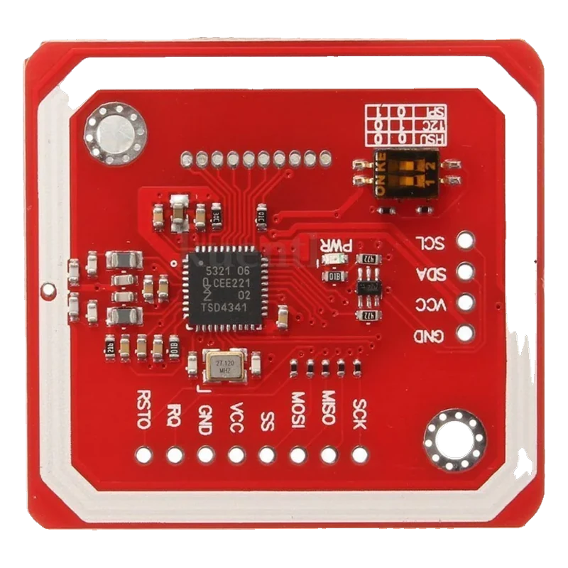
The PN532 V3 module is an NFC reader/writer for 13.56 MHz cards (MIFARE Classic 1K and 4K, Ultralight, DESFire, ISO 14443-4, FeliCa) with a PCB antenna that reads at 5 cm to 7 cm (Elechouse PN532 User Guide V3, p. 2). VCC takes 3.3 V to 5 V, and a two-way DIP switch picks HSU (both off, the default), I2C (switch 1 on) or SPI (switch 2 on) (p. 3). In I2C mode it answers at 0x24 (Adafruit_PN532, PN532_I2C_ADDRESS), and the Adafruit PN532 library reads card UIDs in a few lines.
The PN532 is NXP's NFC controller: an 80C51 core with 40 KB of ROM and 1 KB of RAM that handles the 13.56 MHz radio, the card protocols and the host interface (NXP PN532/C1 short form data sheet Rev. 1.2, p. 2). It reads and writes ISO 14443A/MIFARE and FeliCa cards, can emulate a card, and talks peer-to-peer with phones.
The red V3 module, designed by Elechouse and widely copied, adds the antenna, a level shifter and a small switch that selects the interface. HSU (high-speed UART) is the default; flip switch 1 on for I2C or switch 2 on for SPI (Elechouse PN532 User Guide V3, p. 3). The 4-pin header is printed GND, VCC, SDA and SCL on the front, with TXD and RXD on the back for UART, and a side header carries SCK, MISO, MOSI, SS, VCC, GND, IRQ and RSTO.
Range depends on the card and the antenna: Elechouse quotes 5 cm to 7 cm for V3 (p. 2), within the up to 50 mm NXP gives as typical for reader mode (data sheet, p. 2). Metal behind the card or the module cuts it sharply. For I2C, the Adafruit PN532 library is the common choice; it checks the PN532's ready byte over the bus, so the IRQ line is optional.
PN532 NFC pinout
| Pin | Function | Type |
|---|---|---|
| GND | Ground | power in |
| VCC | Supply3.3 V to 5 V | power in |
| SDA | I2C SDA, UART TX in HSU mode | bidirectional |
| SCL | I2C SCL, UART RX in HSU mode | input |
| SCK | SPI SCK3.3 V TTL, 100 Ω series | input |
| MISO | SPI MISO3.3 V TTL | output |
| MOSI | SPI MOSI3.3 V TTL, 100 Ω series | input |
| SS | SPI CS (active low)3.3 V TTL, 100 Ω series | input |
| IRQ | Interrupt (active low) | output |
| RSTO | Reset output | output |
How to wire the PN532 NFC
Pin by pin, for the board you have.
| PN532 NFC | Arduino Uno | Note |
|---|---|---|
| GND | GND | |
| VCC | 5V | |
| SDA | A4 (SDA) | |
| SCL | A5 (SCL) |
- Set the DIP switch to I2C (switch 1 ON, switch 2 OFF) before powering up.
| PN532 NFC | ESP32 DevKit V1 | Note |
|---|---|---|
| GND | GND | |
| VCC | 3V3 | |
| SDA | GPIO21 (D21) | |
| SCL | GPIO22 (D22) |
- Set the DIP switch to I2C (switch 1 ON, switch 2 OFF).
- Power VCC from 3V3, not VIN: the module's I2C side follows VCC, so 3.3 V keeps SDA and SCL at the ESP32's level.
| PN532 NFC | Raspberry Pi Pico | Note |
|---|---|---|
| GND | GND | |
| VCC | 3V3(OUT) | |
| SDA | GP4 | |
| SCL | GP5 |
- Set the DIP switch to I2C (switch 1 ON, switch 2 OFF).
- Power VCC from 3V3(OUT), not VBUS, so SDA and SCL stay at 3.3 V.
PN532 NFC code
Every example here compiles for its board.
// PN532 NFC on Arduino Uno: wiring and a free simulation at https://www.tinkered.ai/components/pn532-nfc
// PN532 V3 module in I2C mode on an Arduino Uno: SDA A4, SCL A5, address 0x24
#include <Wire.h>
#include <Adafruit_PN532.h>

// The constructor wants IRQ and reset pins; in I2C mode the library reads the PN532's
// ready byte instead, so D2 and D3 stay unconnected here.
Adafruit_PN532 nfc(2, 3, &Wire);

void setup() {
  Serial.begin(115200);
  nfc.begin();
  uint32_t version = nfc.getFirmwareVersion();
  if (!version) {
    Serial.println(F("PN532 not found: check the I2C switch and wiring"));
    while (true) {}
  }
  Serial.print(F("Found PN5"));
  Serial.print((version >> 24) & 0xFF, HEX);
  Serial.print(F(" firmware "));
  Serial.print((version >> 16) & 0xFF);
  Serial.print('.');
  Serial.println((version >> 8) & 0xFF);
  nfc.SAMConfig(); // normal reader mode
  Serial.println(F("Tap a card..."));
}

void loop() {
  uint8_t uid[7];
  uint8_t uidLength;
  if (nfc.readPassiveTargetID(PN532_MIFARE_ISO14443A, uid, &uidLength, 1000)) {
    Serial.print(F("Card UID:"));
    for (uint8_t i = 0; i < uidLength; i++) {
      Serial.print(uid[i] < 0x10 ? F(" 0") : F(" "));
      Serial.print(uid[i], HEX);
    }
    Serial.println();
    delay(1000);
  }
}
// PN532 NFC on ESP32 DevKit V1: wiring and a free simulation at https://www.tinkered.ai/components/pn532-nfc
// PN532 V3 module in I2C mode on an ESP32 DevKit V1: SDA GPIO21, SCL GPIO22, address 0x24
#include <Wire.h>
#include <Adafruit_PN532.h>

// IRQ and reset pins for the constructor; unconnected, the library polls the ready byte over I2C.
Adafruit_PN532 nfc(26, 27, &Wire);

void setup() {
  Serial.begin(115200);
  Wire.begin(21, 22); // SDA, SCL
  nfc.begin();
  uint32_t version = nfc.getFirmwareVersion();
  if (!version) {
    Serial.println("PN532 not found: check the I2C switch and wiring");
    while (true) { delay(100); }
  }
  Serial.printf("Found PN5%02X firmware %u.%u\n", (unsigned)((version >> 24) & 0xFF), (unsigned)((version >> 16) & 0xFF), (unsigned)((version >> 8) & 0xFF));
  nfc.SAMConfig();
  Serial.println("Tap a card...");
}

void loop() {
  uint8_t uid[7];
  uint8_t uidLength;
  if (nfc.readPassiveTargetID(PN532_MIFARE_ISO14443A, uid, &uidLength, 1000)) {
    Serial.print("Card UID:");
    for (uint8_t i = 0; i < uidLength; i++) Serial.printf(" %02X", uid[i]);
    Serial.println();
    delay(1000);
  }
}
// PN532 NFC on Raspberry Pi Pico: wiring and a free simulation at https://www.tinkered.ai/components/pn532-nfc
// PN532 V3 module in I2C mode on a Raspberry Pi Pico (arduino-pico): SDA GP4, SCL GP5, address 0x24
#include <Wire.h>
#include <Adafruit_PN532.h>

// IRQ and reset pins for the constructor; unconnected, the library polls the ready byte over I2C.
Adafruit_PN532 nfc(6, 7, &Wire);

void setup() {
  Serial.begin(115200);
  Wire.setSDA(4);
  Wire.setSCL(5);
  nfc.begin();
  uint32_t version = nfc.getFirmwareVersion();
  if (!version) {
    Serial.println("PN532 not found: check the I2C switch and wiring");
    while (true) { delay(100); }
  }
  Serial.print("Found PN5");
  Serial.print((version >> 24) & 0xFF, HEX);
  Serial.print(" firmware ");
  Serial.print((version >> 16) & 0xFF);
  Serial.print('.');
  Serial.println((version >> 8) & 0xFF);
  nfc.SAMConfig();
  Serial.println("Tap a card...");
}

void loop() {
  uint8_t uid[7];
  uint8_t uidLength;
  if (nfc.readPassiveTargetID(PN532_MIFARE_ISO14443A, uid, &uidLength, 1000)) {
    Serial.print("Card UID:");
    for (uint8_t i = 0; i < uidLength; i++) {
      Serial.print(uid[i] < 0x10 ? " 0" : " ");
      Serial.print(uid[i], HEX);
    }
    Serial.println();
    delay(1000);
  }
}
Before you wire it
- Set the interface switch before power-up: I2C is switch 1 ON and switch 2 OFF (Elechouse PN532 User Guide V3, p. 3).
- Power VCC at your board's logic voltage on 3.3 V boards, so the I2C lines sit at 3.3 V.
- Call SAMConfig() after begin() and before reading cards.
- Keep metal away from the antenna area; Elechouse also asks for wires to cross the antenna traces at 90 degrees (p. 4).
- Never expect the module to answer on I2C with the switch in its default HSU position.
- Never use the Uno's D0 and D1 for HSU mode while you need the Serial Monitor; they are the USB serial port (p. 5).
- Never treat RSTO as a reset input: it is an output of the PN532.
- In I2C mode the Adafruit library checks the PN532's ready byte over the bus, so IRQ can stay unconnected; the IRQ and reset numbers in the constructor are placeholders.
- SPI mode is the fastest and least fussy: its lines are 3.3 V TTL with 100 Ω series resistors, which Elechouse says connect directly to a 5 V Arduino (p. 3).
- The PN532 itself runs from 2.7 V to 5.4 V and uses a 1.6 V to 3.6 V supply for its host interface (NXP data sheet, p. 3); the module's level shifter bridges it to the header.
- A tag must sit flat over the antenna; a phone case, a metal table or a coin underneath can halve the range.
- MIFARE Classic sectors need the right key to read data; UID reads and NTAG pages need no key.
Specifications
- Chip supply (VBAT)
- 2.7 V to 5.4 V; host interface supply PVDD 1.6 V to 3.6 VNXP PN532/C1 short form data sheet Rev. 1.2, p. 3
- Module supply
- VCC 3.3 V to 5 VElechouse PN532 NFC RFID Module User Guide V3, p. 3
- Module logic
- On-board level shifter: I2C and UART specified 3.3 V to 24 V TTL; SPI 3.3 V TTL with 100 Ω series resistorsElechouse PN532 User Guide V3, pp. 2 to 3
- Interface switch
- HSU: both off (default); I2C: switch 1 on, 2 off; SPI: switch 1 off, 2 onElechouse PN532 User Guide V3, p. 3
- I2C address
- 0x24 (0x48 >> 1)Adafruit_PN532 library, PN532_I2C_ADDRESS
- Cards
- MIFARE 1K, 4K, Ultralight, DESFire; ISO/IEC 14443-4; Innovision Jewel; FeliCaElechouse PN532 User Guide V3, p. 2
- Reading distance
- 5 cm to 7 cm (module); up to 50 mm typical in reader mode (chip)Elechouse PN532 User Guide V3, p. 2; NXP PN532/C1 data sheet, p. 2
- Power-down current
- 2 µA hard power-down, 10 µA soft power-down (VBAT 5 V)NXP PN532/C1 short form data sheet Rev. 1.2, p. 3
- Size
- 42.7 × 40.4 × 4 mmElechouse PN532 User Guide V3, p. 2
From the NXP PN532/C1 NFC controller short form data sheet Rev. 1.2, published by NXP Semiconductors (PN532), module by Elechouse.
Common mistakes
Switch left in HSU mode
Out of the box the module talks UART (both switches off, Elechouse User Guide V3, p. 3). An I2C scanner finds nothing until switch 1 is on and switch 2 off, and the module is power-cycled.
SDA and SCL swapped with TXD and RXD
The same two pins carry I2C (front labels) and UART (back labels). Read the front for SDA and SCL when the switch is set to I2C.
Powering it at 5 V on a 3.3 V board
The level-shifted I2C lines follow the module's VCC. On an ESP32 or Pico, feed VCC from 3.3 V so the bus does not idle at 5 V.
Wrong library for the module
Code written for the MFRC522 (RC522 modules) does not drive the PN532. Use Adafruit PN532 or Elechouse's PN532 library.
PN532 NFC questions
What is the PN532's I2C address?
0x24 as a 7-bit address (0x48 written as an 8-bit address), as the Adafruit library defines it. The address is fixed; only the interface switch changes how the module talks.
How do I set the PN532 V3 to I2C mode?
Set switch 1 ON and switch 2 OFF; SPI is switch 1 OFF and switch 2 ON; both OFF is HSU (UART), the default (Elechouse PN532 User Guide V3, p. 3). Change it with the power off.
What is the reading range of the PN532?
Elechouse quotes 5 cm to 7 cm for the V3 module (p. 2), and NXP up to 50 mm typical in reader mode, depending on antenna and card (NXP data sheet, p. 2). Small key fobs read closer than full-size cards.
PN532 or RC522?
The RC522 (MFRC522) is cheaper and reads MIFARE cards over SPI. The PN532 adds FeliCa, ISO 14443-4, card emulation and phone peer-to-peer, and offers I2C and UART as well as SPI.
Can the PN532 read my phone or bank card?
It can detect them and read their UID, which on phones is usually random. Payment data is encrypted; NFC tags such as NTAG215 and MIFARE cards are what makers read and write.
Build something with the PN532 NFC
- Build this
NFC door lock
Only listed cards switch the relay that opens the lock.
- Build this
NFC attendance logger
Log each card tap with a timestamp.
This page as plain Markdown, for ChatGPT, Claude or your own agent. /components/pn532-nfc.md