HX711 Load Cell Amplifier
A 24-bit ADC with a gain-128 amplifier, built to read load cells and turn a strain gauge bridge into a digital scale.
- Resolution24-bit, two's complement (800000h to 7FFFFFh)
- Gain and full scaleCh A: 128 (±20 mV) or 64 (±40 mV); Ch B: 32 (±80 mV), at AVDD = 5 V
- Supply voltage2.6 V to 5.5 V (VSUP regulator input 2.7 V to 5.5 V)
- CurrentUnder 1.5 mA running, under 1 µA powered down
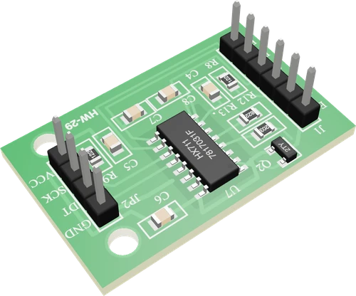
The HX711 is a 24-bit ADC with a programmable gain amplifier that reads a load cell's millivolt bridge output; channel A runs at gain 128 or 64 and channel B at gain 32 (Avia HX711 datasheet V2.0, p. 1). Wire the cell to E+, E-, A+ and A-, the module's VCC to 2.6 V to 5.5 V, and DT and SCK to any two digital pins (pp. 1, 2). DT goes low when a reading is ready and the code clocks out 24 bits on SCK (p. 4); then tare and calibrate with a known weight.
The HX711 from Avia Semiconductor is a precision 24-bit analog-to-digital converter made for weigh scales. A low-noise programmable gain amplifier sits in front of it: channel A takes gain 128 or 64, a full scale of ±20 mV or ±40 mV with a 5 V analog supply, and channel B has a fixed gain of 32, ±80 mV (Avia datasheet, pp. 1, 4). That is the range of a load cell's bridge output, a few millivolts at full load.
It also excites the load cell itself. An on-chip regulator drives an external transistor to set the analog supply, AVDD = VBG × (R1 + R2) / R2 with VBG = 1.25 V, and AVDD must sit at least 100 mV below the supply (pp. 3, 4). The common green module uses that regulator to put about 4.3 V on E+, with E- at ground. Its RATE pin is tied low, so it converts 10 times a second; RATE high gives 80 (p. 2).
There is no I2C or SPI. The HX711 holds DOUT high until a conversion is ready, then pulls it low; the host sends 25 to 27 clock pulses on PD_SCK to shift out 24 bits, MSB first, in two's complement, and the extra pulses choose the next channel and gain: 25 for A at 128, 26 for B at 32, 27 for A at 64 (p. 4). Holding PD_SCK high for more than 60 µs powers the chip, and the load cell, down (p. 5). Libraries such as HX711 handle all of this.
HX711 Load Cell Amplifier pinout
| Pin | Function | Type |
|---|---|---|
| E_PLUS | E+ (excitation +, 4.3 V) | power out |
| E_MINUS | E− (excitation −) | passive |
| A_MINUS | ADC the bridge's − output (white wire) | input |
| A_PLUS | ADC the bridge's + output (green wire) | input |
| B_MINUS | ADC a second bridge's − output, gain 32 | input |
| B_PLUS | ADC a second bridge's + output, gain 32 | input |
| GND | GND | power in |
| DT | Digital | output |
| SCK | Digital | input |
| VCC | VCC (2.6-5.5 V)2.6–5 V | power in |
How to wire the HX711 Load Cell Amplifier
Pin by pin, for the board you have.
| HX711 Load Cell Amplifier | Arduino Uno | Note |
|---|---|---|
| VCC | 5V | |
| GND | GND | |
| DT | D3 | |
| SCK | D2 |
| HX711 Load Cell Amplifier | ESP32 DevKit V1 | Note |
|---|---|---|
| VCC | 3V3 | |
| GND | GND | |
| DT | GPIO13 (D13) | |
| SCK | GPIO14 (D14) |
| HX711 Load Cell Amplifier | Raspberry Pi Pico | Note |
|---|---|---|
| VCC | 3V3 | |
| GND | GND | |
| DT | GP0 | |
| SCK | GP1 |
HX711 Load Cell Amplifier code
Every example here compiles for its board.
// HX711 Load Cell Amplifier on Arduino Uno: wiring and a free simulation at https://www.tinkered.ai/components/hx711-module
#include "HX711.h"

const int DT_PIN = 3;    // HX711 DT (DOUT)
const int SCK_PIN = 2;   // HX711 SCK
// counts per gram: about 430 for a 5 kg bar (2150 at 1 kg, 215 at 10 kg); calibrate with a known weight
const float CALIBRATION = 430.0;

HX711 scale;

void setup() {
  Serial.begin(9600);
  scale.begin(DT_PIN, SCK_PIN);
  Serial.println("HX711 scale");
  while (!scale.is_ready()) delay(10);   // its first reading comes 0.4 s after power-up
  scale.set_scale(CALIBRATION);
  scale.tare(10);                        // the empty scale's zero, averaged
  Serial.println("Tared: put a weight on it");
}

void loop() {
  if (scale.is_ready()) {
    float grams = scale.get_units(5);    // the average of 5 readings, tared and scaled
    Serial.print("Weight: ");
    Serial.print(grams, 1);
    Serial.println(" g");
  }
  delay(500);
}
// HX711 Load Cell Amplifier on ESP32 DevKit V1: wiring and a free simulation at https://www.tinkered.ai/components/hx711-module
#include "HX711.h"

const int DT_PIN = 13;    // HX711 DT (DOUT)
const int SCK_PIN = 14;   // HX711 SCK
// counts per gram: about 430 for a 5 kg bar (2150 at 1 kg, 215 at 10 kg); calibrate with a known weight
const float CALIBRATION = 430.0;

HX711 scale;

void setup() {
  Serial.begin(9600);
  scale.begin(DT_PIN, SCK_PIN);
  Serial.println("HX711 scale");
  while (!scale.is_ready()) delay(10);   // its first reading comes 0.4 s after power-up
  scale.set_scale(CALIBRATION);
  scale.tare(10);                        // the empty scale's zero, averaged
  Serial.println("Tared: put a weight on it");
}

void loop() {
  if (scale.is_ready()) {
    float grams = scale.get_units(5);    // the average of 5 readings, tared and scaled
    Serial.print("Weight: ");
    Serial.print(grams, 1);
    Serial.println(" g");
  }
  delay(500);
}
// HX711 Load Cell Amplifier on Raspberry Pi Pico: wiring and a free simulation at https://www.tinkered.ai/components/hx711-module
#include "HX711.h"

const int DT_PIN = 0;    // HX711 DT (DOUT)
const int SCK_PIN = 1;   // HX711 SCK
// counts per gram: about 430 for a 5 kg bar (2150 at 1 kg, 215 at 10 kg); calibrate with a known weight
const float CALIBRATION = 430.0;

HX711 scale;

void setup() {
  Serial.begin(9600);
  scale.begin(DT_PIN, SCK_PIN);
  Serial.println("HX711 scale");
  while (!scale.is_ready()) delay(10);   // its first reading comes 0.4 s after power-up
  scale.set_scale(CALIBRATION);
  scale.tare(10);                        // the empty scale's zero, averaged
  Serial.println("Tared: put a weight on it");
}

void loop() {
  if (scale.is_ready()) {
    float grams = scale.get_units(5);    // the average of 5 readings, tared and scaled
    Serial.print("Weight: ");
    Serial.print(grams, 1);
    Serial.println(" g");
  }
  delay(500);
}
Before you wire it
- VCC to the board's logic supply: 5V on an Uno, Nano, Mega or UNO R4; 3V3 on an ESP32, ESP32-S3, ESP32-C3, ESP8266 or Pico (DT's HIGH is VCC). GND to GND.
- DT and SCK to two digital pins (any; avoid an ESP32's GPIO 6-11 and its strapping pins 0, 2, 12, 15). DT is the HX711's output: the sketch reads it; SCK is driven by the sketch.
- The load cell on J1: red E+, black E−, green A+, white A−. Never on the board's analog pins: its output is about 1 mV per volt at full load.
- Use the library HX711.h with lib_deps = robtillaart/HX711 (the compute image bakes it; its calls are bogde's: begin(dataPin, clockPin), is_ready(), read(), tare(n), set_scale(f), get_units(n), set_gain(), power_down()/power_up()).
- In setup(): begin(DT, SCK), wait for is_ready(), set_scale(factor), then tare(10) on the EMPTY scale.
- Average: get_units(5) or more. Read only when is_ready() (or use wait_ready_timeout(1000)): read() blocks until DT goes LOW, forever when the HX711 is unpowered.
- No analogRead() of the load cell or of DT.
- No pulseIn()/shiftIn() hand-rolled protocols: use the library.
- No hard-coded zero ("raw - 8388608"): tare at start-up.
- No 5 V on VCC with a 3.3 V board.
- Do not promise an accuracy past the cell's: about ±0.05 % of capacity, and only after calibrating with a known weight.
- Load cell to the module: red to E+, black to E-, green to A+, white to A-. Channel B (B+, B-) is a second input at gain 32.
- Power VCC from the same supply as the microcontroller, as Avia asks for the digital supply (datasheet, p. 4): 5 V on an Uno, 3.3 V on an ESP32, ESP8266 or Pico, so DT's high level matches the board.
- On 5 V the module's regulator holds E+ at about 4.3 V. On 3.3 V it cannot, because AVDD must stay 100 mV below the supply (p. 4): the cell's excitation drops and so does its output, which calibration absorbs.
- DT and SCK go to any two digital pins. Keep each SCK high pulse between 0.2 µs and 50 µs (p. 5); a pulse longer than 60 µs, for example when an interrupt lands mid-read, powers the chip down (p. 5).
- The first valid reading arrives 400 ms after power-up at 10 SPS (p. 3), so wait for DT to go low before taring.
Specifications
- Resolution
- 24-bit, two's complement (800000h to 7FFFFFh)Avia HX711 datasheet V2.0, pp. 1, 3
- Gain and full scale
- Ch A: 128 (±20 mV) or 64 (±40 mV); Ch B: 32 (±80 mV), at AVDD = 5 VAvia HX711 datasheet V2.0, pp. 1, 4
- Supply voltage
- 2.6 V to 5.5 V (VSUP regulator input 2.7 V to 5.5 V)Avia HX711 datasheet V2.0, pp. 1, 2
- Current
- Under 1.5 mA running, under 1 µA powered downAvia HX711 datasheet V2.0, p. 1
- Output data rate
- 10 SPS (RATE low) or 80 SPS (RATE high)Avia HX711 datasheet V2.0, pp. 1, 2
- Settling time
- 400 ms at 10 SPS, 50 ms at 80 SPSAvia HX711 datasheet V2.0, p. 3
- Input noise
- 50 nV rms at gain 128, 10 SPSAvia HX711 datasheet V2.0, p. 3
- Mains rejection
- Simultaneous 50 Hz and 60 Hz rejectionAvia HX711 datasheet V2.0, p. 1
- Power down
- PD_SCK high for more than 60 µsAvia HX711 datasheet V2.0, p. 5
- Excitation regulator
- AVDD = 1.25 V × (R1 + R2) / R2, at least 100 mV below VSUPAvia HX711 datasheet V2.0, pp. 3, 4
- Maximum supply voltage
- 5.5 V
- Interface
- Digital
- Dimensions
- 21 × 34 × 11.1 mm
- Weight
- 2.5 g
From the Avia Semiconductor (HX711); generic module's datasheet, published by Avia Semiconductor (HX711); generic module.
Common mistakes
Skipping tare and calibration
A raw HX711 count is never zero with an empty scale: the cell's zero unbalance and the chip's offset add up. Tare the empty scale at start-up, then divide by a calibration factor found with a known weight.
Crossed signal or excitation wires
Swapping green and white (A+ and A-) makes the weight read negative; leaving E+ or E- open gives readings that jump by millions or saturate at 7FFFFFh or 800000h (Avia datasheet, p. 4).
5 V VCC on a 3.3 V board
DT swings to VCC. Powered from 5 V, it drives 5 V into an ESP32 or Pico input. Power the module from the board's 3.3 V.
Interrupts stretching the SCK pulse
If SCK stays high for more than 60 µs the HX711 powers down mid-read (p. 5) and the value is lost. Use a library that keeps interrupts off during the 24-bit read, as most do.
Reading on channel B by mistake
Channel B has a fixed gain of 32, a quarter of channel A's 128 (p. 1). A cell on B+ and B- reads about four times smaller; move it to A or set the gain to 32 and recalibrate.
HX711 Load Cell Amplifier questions
Does the HX711 work at 3.3 V with an ESP32?
Yes. The HX711 runs from 2.6 V to 5.5 V (Avia datasheet, p. 1), so power the module from the ESP32's 3.3 V and its DT output matches the ESP32's logic. The load cell's excitation then falls below the 4.3 V it gets on 5 V, since AVDD must sit 100 mV under the supply (p. 4); calibrate on the supply you will use.
Why does my HX711 read huge random numbers or never change?
Values jumping by millions or stuck near 8,388,607 (7FFFFFh) mean the bridge input is open or saturated (Avia datasheet, p. 4): check E+, E-, A+ and A-. A sketch that hangs means DT never goes low, so the chip is unpowered or DT and SCK are swapped; DT stays high until a conversion is ready (p. 4).
How do I calibrate an HX711 scale?
Tare with the scale empty, place a known weight, and divide the tared reading by that weight in grams to get counts per gram. Use that factor in the library's set_scale(). A negative factor means A+ and A- are crossed.
What is the HX711 sample rate?
10 samples per second with RATE low, 80 with RATE high (Avia datasheet, pp. 1, 2). The common green module ties RATE low, so it reads at 10 SPS. At 80 SPS input noise rises from 50 to 90 nV rms (p. 3).
Can one HX711 read two load cells?
Yes, on its two channels: A at gain 128 or 64 and B at gain 32 (Avia datasheet, p. 1), selected by the number of clock pulses after each read (p. 4). Channel B's lower gain makes it less sensitive. Four half-bridge cells in a bathroom scale instead combine into one full bridge on channel A.
What do the HX711 pins E+, E-, A+, A- mean?
E+ and E- are the excitation supply for the load cell's bridge, A+ and A- the bridge's differential output into channel A, and B+ and B- a second input at gain 32. On the MCU side, DT is the chip's data output DOUT and SCK its clock and power-down input PD_SCK (Avia datasheet, p. 2).
Build something with the HX711 Load Cell Amplifier
- Build this
Kitchen scale
A straight bar load cell under a platform, read in grams on an LCD or OLED.
- Build this
Beehive or plant weight logger
Log a hive's or a pot's weight over days to track honey flow or watering.
- Build this
Pet feeder that weighs portions
Stop a servo-driven dispenser once the bowl reaches a target weight.
- Build this
Filament spool scale
Show how much 3D printer filament is left on a spool.
- Build this
Force and thrust test stand
Measure a motor and propeller's thrust or a spring's force.
This page as plain Markdown, for ChatGPT, Claude or your own agent. /components/hx711-module.md