MQ-135
A tin-dioxide gas sensor module that reacts to ammonia, benzene-type vapours, smoke and other pollutants, giving an analog voltage and a threshold output for air quality alarms.
- Heater voltage5.0 V ±0.1 V, AC or DC
- Heater resistance and power29 Ω ±3 Ω at room temperature (about 170 mA at 5 V); 950 mW max
- Circuit (loop) voltage24 V DC max
- Target gasesAmmonia, sulfide, benzene-series vapour; also smoke and other harmful gases
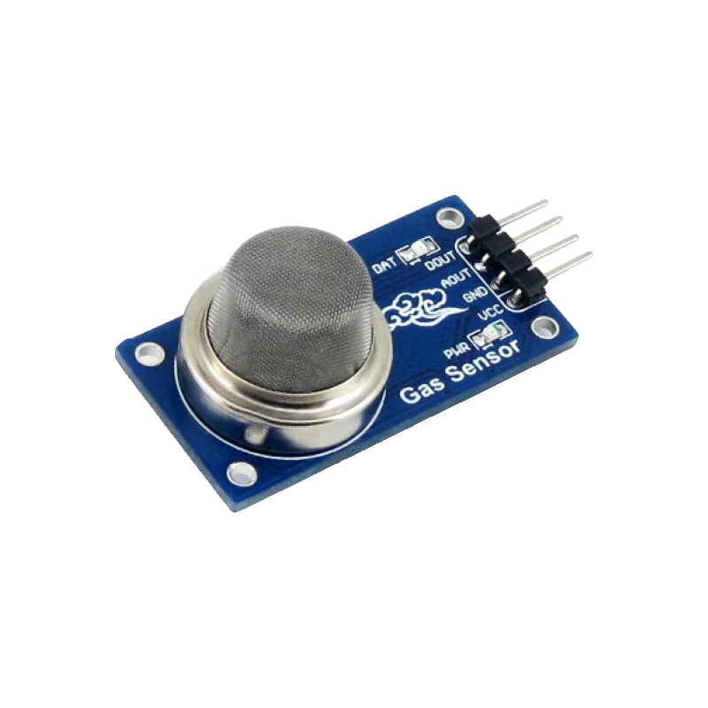
The MQ-135 is a heated tin-dioxide (SnO2) sensor whose resistance falls as ammonia, sulfides, benzene-series vapours, smoke and similar gases rise, over a 10 to 1000 ppm detection range (Winsen MQ135 manual Ver1.4, p. 3). Its heater needs 5.0 V ±0.1 V across 29 Ω, about 170 mA and up to 950 mW, and the maker specifies it after more than 48 hours of preheat (p. 3). On the 4-pin module, power VCC from 5 V and read AOUT on an analog pin, through a divider on 3.3 V boards.
The MQ-135's sensing layer is tin dioxide, which conducts poorly in clean air and better as reducing and polluting gases reach it. Winsen lists it for ammonia, sulfide and benzene-series vapours, with a detection range of 10 to 1000 ppm for gases such as ammonia, toluene and hydrogen, and good response to smoke (Winsen manual Ver1.4, p. 3). It responds to many gases at once, so it gives an air quality trend, not a concentration of any one gas.
A small heater keeps the layer at working temperature: 5.0 V ±0.1 V across 29 Ω ±3 Ω, so about 170 mA and up to 950 mW (p. 3). The sensor's resistance (Rs) forms a divider with a load resistor; the maker's curves plot Rs/R0, the resistance relative to clean air, against concentration (p. 4). Characterisation assumes 20 °C, 55 %RH and over 48 hours of preheat (p. 3), and humidity and temperature shift the curves.
Modules such as Waveshare's put the sensor on a 40 × 21 mm board with a load resistor, a comparator and a sensitivity trimmer, and bring out VCC, GND, AOUT and DOUT (Waveshare product page). AOUT rises toward the supply as pollution increases; DOUT switches when AOUT crosses the trimmer's threshold.
MQ-135 pinout
| Pin | Function | Type |
|---|---|---|
| VCC | VCC5 V for the heater (5.0 V ±0.1 V) | power in |
| GND | GND | power in |
| AOUT | ADC0 V to VCC | output |
| DOUT | Digital thresholdSwings to VCC | output |
How to wire the MQ-135
Pin by pin, for the board you have.
| MQ-135 | Arduino Uno | Note |
|---|---|---|
| VCC | 5V | |
| GND | GND | |
| AOUT | A0 |
- DOUT is left unwired: the sketch sets its alarm from AOUT. You can wire DOUT to D2 on an Uno (5 V logic) if you prefer the trimmer threshold.
| MQ-135 | ESP32 DevKit V1 | Note |
|---|---|---|
| VCC | VIN | |
| GND | GND | |
| AOUT | GPIO34 (D34) | Through a 10 kΩ resistor, with a 15 kΩ resistor from GPIO34 to GND: the divider scales 5 V down to 3.0 V. |
- VIN gives 5 V only while the DevKit is on USB; the heater needs 5 V and about 170 mA.
- DOUT is left unwired: it swings to 5 V. The sketch alarms from AOUT instead.
| MQ-135 | Raspberry Pi Pico | Note |
|---|---|---|
| VCC | VBUS | |
| GND | GND | |
| AOUT | GP26 | Through a 10 kΩ resistor, with a 15 kΩ resistor from GP26 to GND: the divider scales 5 V down to 3.0 V. |
- VBUS is 5 V only while the Pico is on USB.
- DOUT is left unwired: it swings to 5 V. The sketch alarms from AOUT instead.
MQ-135 code
Every example here compiles for its board.
// MQ-135 on Arduino Uno: wiring and a free simulation at https://www.tinkered.ai/components/mq-135
// MQ-135 module on an Arduino Uno: VCC 5V, AOUT to A0 (10-bit ADC, 5 V reference)
const int PIN_AOUT = A0;

float readAoutVolts() {
  return analogRead(PIN_AOUT) * 5.0 / 1023.0;
}

float baselineV = 0;

void setup() {
  Serial.begin(115200);

  Serial.println("MQ-135: heater warming. Readings drift for the first minutes;");
  Serial.println("the maker conditions sensors for 48 h before specifying them.");
  delay(60000);  // at least a minute of heater warm-up before taking a baseline
  float sum = 0;
  for (int i = 0; i < 20; i++) { sum += readAoutVolts(); delay(250); }
  baselineV = sum / 20.0;
  Serial.print("Clean-air baseline: ");
  Serial.print(baselineV, 3);
  Serial.println(" V");
}

void loop() {
  float v = readAoutVolts();
  float change = (v - baselineV) / baselineV * 100.0;
  Serial.print("AOUT: ");
  Serial.print(v, 3);
  Serial.print(" V   change from baseline: ");
  Serial.print(change, 1);
  Serial.print(" %");
  if (change > 50.0) Serial.print("   POOR AIR");
  Serial.println();
  delay(1000);
}
// MQ-135 on ESP32 DevKit V1: wiring and a free simulation at https://www.tinkered.ai/components/mq-135
// MQ-135 module on an ESP32 DevKit V1: VCC VIN (5 V), AOUT to GPIO34 through a 10k/15k divider
const int PIN_AOUT = 34;                    // ADC1, input only
const float DIVIDER = (10.0 + 15.0) / 15.0;  // 10 kΩ top, 15 kΩ bottom

float readAoutVolts() {
  return analogReadMilliVolts(PIN_AOUT) / 1000.0 * DIVIDER;
}

float baselineV = 0;

void setup() {
  Serial.begin(115200);

  Serial.println("MQ-135: heater warming. Readings drift for the first minutes;");
  Serial.println("the maker conditions sensors for 48 h before specifying them.");
  delay(60000);  // at least a minute of heater warm-up before taking a baseline
  float sum = 0;
  for (int i = 0; i < 20; i++) { sum += readAoutVolts(); delay(250); }
  baselineV = sum / 20.0;
  Serial.print("Clean-air baseline: ");
  Serial.print(baselineV, 3);
  Serial.println(" V");
}

void loop() {
  float v = readAoutVolts();
  float change = (v - baselineV) / baselineV * 100.0;
  Serial.print("AOUT: ");
  Serial.print(v, 3);
  Serial.print(" V   change from baseline: ");
  Serial.print(change, 1);
  Serial.print(" %");
  if (change > 50.0) Serial.print("   POOR AIR");
  Serial.println();
  delay(1000);
}
// MQ-135 on Raspberry Pi Pico: wiring and a free simulation at https://www.tinkered.ai/components/mq-135
// MQ-135 module on a Raspberry Pi Pico (arduino-pico): VCC VBUS, AOUT to GP26 through a 10k/15k divider
const int PIN_AOUT = 26;                    // ADC0
const float DIVIDER = (10.0 + 15.0) / 15.0;  // 10 kΩ top, 15 kΩ bottom

float readAoutVolts() {
  return analogRead(PIN_AOUT) * 3.3 / 4095.0 * DIVIDER;
}

float baselineV = 0;

void setup() {
  Serial.begin(115200);
  analogReadResolution(12);  // 0 to 4095 over 3.3 V
  Serial.println("MQ-135: heater warming. Readings drift for the first minutes;");
  Serial.println("the maker conditions sensors for 48 h before specifying them.");
  delay(60000);  // at least a minute of heater warm-up before taking a baseline
  float sum = 0;
  for (int i = 0; i < 20; i++) { sum += readAoutVolts(); delay(250); }
  baselineV = sum / 20.0;
  Serial.print("Clean-air baseline: ");
  Serial.print(baselineV, 3);
  Serial.println(" V");
}

void loop() {
  float v = readAoutVolts();
  float change = (v - baselineV) / baselineV * 100.0;
  Serial.print("AOUT: ");
  Serial.print(v, 3);
  Serial.print(" V   change from baseline: ");
  Serial.print(change, 1);
  Serial.print(" %");
  if (change > 50.0) Serial.print("   POOR AIR");
  Serial.println();
  delay(1000);
}
Before you wire it
- Power the heater from a steady 5.0 V ±0.1 V (manual, p. 3); a sagging supply changes every reading.
- Budget about 170 mA for the heater (5 V across 29 Ω, p. 3) on top of the board.
- Let a new sensor burn in: the maker specifies it after more than 48 hours of preheat (p. 3), and readings drift until then.
- Use a divider on AOUT for any 3.3 V board: AOUT can reach the 5 V supply.
- Never expose it to silicone vapour (sealants, silicone adhesives): the layer loses sensitivity permanently (p. 5).
- Never let it get wet or freeze (p. 6).
- Never apply more than the rated heater voltage, and on a bare 6-pin sensor never put voltage across the measuring pins 1-3 or 4-6 as if they were the heater (p. 6).
- Never treat it as a calibrated CO2 meter: it reacts to many gases at once. Use an NDIR sensor such as the MH-Z19B for CO2.
- The heater gets hot: keep the sensor's mesh away from plastics and leave air around it.
- AOUT is the voltage across the module's load resistor; the sensor resistance is Rs = RL × (VCC - Vout) / Vout once you know RL from the board.
- Characterisation is at 20 °C and 55 %RH (p. 3); temperature and humidity shift the response (p. 4), so pair it with a temperature and humidity sensor for compensation.
- On the ESP32, use an ADC1 pin such as GPIO34: ADC2 pins stop working while Wi-Fi is on.
Specifications
- Heater voltage
- 5.0 V ±0.1 V, AC or DCWinsen MQ135 manual Ver1.4 (2015), p. 3
- Heater resistance and power
- 29 Ω ±3 Ω at room temperature (about 170 mA at 5 V); 950 mW maxWinsen MQ135 manual Ver1.4 (2015), p. 3
- Circuit (loop) voltage
- 24 V DC maxWinsen MQ135 manual Ver1.4 (2015), p. 3
- Target gases
- Ammonia, sulfide, benzene-series vapour; also smoke and other harmful gasesWinsen MQ135 manual Ver1.4 (2015), p. 3
- Detection range
- 10 to 1000 ppm (ammonia, toluene, hydrogen, smoke)Winsen MQ135 manual Ver1.4 (2015), p. 3
- Sensitivity
- Rs(in air) / Rs(in 400 ppm H2) of at least 5Winsen MQ135 manual Ver1.4 (2015), p. 3
- Preheat
- Over 48 hours for specified performance; test at 20 °C ±2 °C, 55 %RH ±5 %RHWinsen MQ135 manual Ver1.4 (2015), p. 3
- Module
- 2.5 V to 5.0 V supply, 40 × 21 mm, pins VCC, GND, AOUT, DOUT, adjustable sensitivityWaveshare MQ-135 Gas Sensor product page
From the MQ135 manual Ver1.4, published by Zhengzhou Winsen Electronics.
Common mistakes
Reading 'ppm of CO2' from a library
Some libraries convert the MQ-135 to CO2 ppm with a fixed curve. The sensor responds to ammonia, benzene vapours, smoke and more (manual, p. 3), and its R0 differs part to part, so that number is an estimate at best.
Feeding 5 V AOUT into an ESP32 or Pico
With VCC at 5 V, AOUT can reach 5 V. Add the 10 kΩ and 15 kΩ divider, which brings 5 V to 3.0 V.
Judging it in the first hour
A new sensor reads high and drifts while the layer stabilises; the maker's figures assume over 48 hours of preheat (p. 3). Take baselines after burn-in.
Board browns out
The heater draws about 170 mA. On a weak supply the 5 V rail sags, shifting the reading and sometimes resetting the board.
MQ-135 questions
What does the MQ-135 actually detect?
Winsen lists ammonia, sulfides and benzene-series vapours, with a 10 to 1000 ppm range for ammonia, toluene, hydrogen and smoke (MQ135 manual Ver1.4, p. 3). It responds to all of them together, which makes it an air quality trend sensor.
Can the MQ-135 measure CO2?
Not reliably. CO2 is not among the gases Winsen specifies it for, and its reading mixes many gases. For CO2 use an NDIR sensor such as the MH-Z19B or SCD41.
Does it work on 3.3 V?
The heater needs 5.0 V ±0.1 V (p. 3), so power the module from 5 V even with a 3.3 V board, and scale AOUT with a divider before the ADC.
How long does it need to warm up?
A minute or two to read sensibly from cold, but Winsen specifies the sensor after more than 48 hours of preheat (p. 3). Run a new sensor for two days before calibrating.
MQ-135 or MQ-2?
Both are SnO2 sensors. The MQ-2 targets combustible gases like LPG, propane and methane; the MQ-135 targets ammonia, benzene-type vapours and smoke, the usual 'air quality' gases.
Build something with the MQ-135
- Build this
Air quality alarm
Beep when the air gets noticeably worse than the clean-air baseline.
- Build this
Kitchen fume monitor
Switch on an extractor fan through a relay when cooking fumes rise.
- Build this
Air trend logger
Log the sensor voltage with temperature and humidity for a day.
This page as plain Markdown, for ChatGPT, Claude or your own agent. /components/mq-135.md