MAX30102 Pulse Oximeter
A pulse oximeter and heart-rate sensor: red and infrared LEDs, a photodetector and an 18-bit ADC behind one window, read over I2C.
- LED wavelengthsRed 660 nm (650 to 670); IR 880 nm (870 to 900)
- ADC18-bit sigma-delta, ambient light cancellation
- Chip suppliesVDD 1.7 V to 2.0 V (1.8 V typical); VLED+ 3.1 V to 5.0 V
- Current600 µA typical at 50 sps; 0.7 µA typical in shutdown
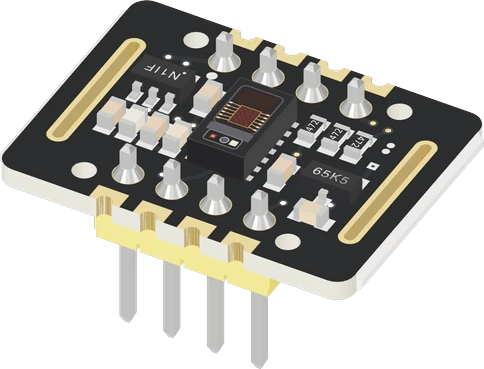
The MAX30102 is Maxim's pulse oximetry and heart-rate sensor: a 660 nm red LED, an 880 nm infrared LED, a photodetector and an 18-bit ADC in one 5.6 × 3.3 mm module, read over I2C at address 0x57 (write 0xAE, read 0xAF) (Maxim MAX30102 datasheet 19-7740 Rev 1, pp. 1, 3, 4, 5). The bare chip needs 1.8 V for its logic and 3.1 V to 5 V for its LEDs (p. 2), so most makers use a module with both regulators: wire VIN to 3.3 V or 5 V, GND to GND, and SDA and SCL to the I2C pins. It outputs raw red and IR counts; heart rate and SpO2 come from an algorithm in your code.
The MAX30102 is an integrated pulse oximetry and heart-rate monitor module from Maxim Integrated, now part of Analog Devices. Inside one 14-pin optical package with a cover glass it holds a red LED (660 nm typical) and an infrared LED (880 nm typical), a photodetector, ambient light cancellation and an 18-bit sigma-delta ADC (Maxim datasheet Rev 1, pp. 1, 3, 4, 9). Placed under a fingertip, the LEDs light the skin and the detector measures how much light comes back; each heartbeat's pulse of blood changes that slightly, and the ratio of red to infrared absorption gives the blood's oxygen saturation.
The chip runs its logic from 1.7 V to 2.0 V and its LEDs from 3.1 V to 5.0 V (p. 2), which is why it is almost always bought on a breakout. The black MH-ET LIVE board adds 1.8 V and 3.3 V regulators fed from VIN (3.3 V to 5 V), 4.7 kΩ pull-ups on SDA, SCL and INT, and two rows of pins: VIN, SDA, SCL, GND, and GND, RD, IRD, INT. RD and IRD come from the older MAX30100 layout and are not connected on the MAX30102.
The chip is configured through registers: sample rate from 50 to 3200 samples per second, LED current from 0 to 50 mA, and LED pulse width from 69 µs to 411 µs (p. 9). Samples land in a 32-sample FIFO (p. 14), and an open-drain, active-low INT pin can signal new data (p. 8). It also carries a die temperature sensor with 0.0625 °C resolution and ±1 °C accuracy (pp. 4, 9), and shuts down to 0.7 µA through software (p. 2).
MAX30102 Pulse Oximeter pinout
| Pin | Function | Type |
|---|---|---|
| VIN | VIN: 3.3-5 V (into the board's 1.8 V and 3.3 V regulators)3.3–5 V | power in |
| SDA | I2C SDA | bidirectional |
| SCL | I2C SCL | bidirectional |
| GND | GND | power in |
| GND_2 | GND (the INT row's, the same ground) | power in |
| RD | RD: the MAX30100 layout's red LED drive pad, unconnected on the MAX30102 | free |
| IRD | IRD: the MAX30100 layout's IR LED drive pad, unconnected on the MAX30102 | free |
| INT | Digital | open collector |
How to wire the MAX30102 Pulse Oximeter
Pin by pin, for the board you have.
| MAX30102 Pulse Oximeter | Arduino Uno | Note |
|---|---|---|
| VIN | 5V | |
| GND | GND | |
| SDA | SDA | |
| SCL | SCL |
| MAX30102 Pulse Oximeter | ESP32 DevKit V1 | Note |
|---|---|---|
| VIN | 3V3 | |
| GND | GND | |
| SDA | GPIO21 (D21) | |
| SCL | GPIO22 (D22) |
| MAX30102 Pulse Oximeter | Raspberry Pi Pico | Note |
|---|---|---|
| VIN | 3V3 | |
| GND | GND | |
| SDA | GP4 | |
| SCL | GP5 |
MAX30102 Pulse Oximeter code
Every example here compiles for its board.
// MAX30102 Pulse Oximeter on Arduino Uno: wiring and a free simulation at https://www.tinkered.ai/components/max30102
#include <Wire.h>
#include "MAX30105.h"
#include "heartRate.h"

MAX30105 sensor;
const byte RATE_SIZE = 4;
byte rates[RATE_SIZE];
byte rateSpot = 0;
long lastBeat = 0;
float beatsPerMinute = 0;
int beatAvg = 0;

void setup() {
  Serial.begin(115200);
  if (!sensor.begin(Wire, I2C_SPEED_FAST)) {
    Serial.println("MAX30102 not found");
    while (1) delay(10);
  }
  sensor.setup();                     // 6.4 mA LEDs, 4 averaged at 400 sps, 411 us, 4096 nA
  sensor.setPulseAmplitudeRed(0x0A);  // red dimmed: heart rate uses the IR channel
  sensor.setPulseAmplitudeGreen(0);
}

void loop() {
  long ir = sensor.getIR();
  if (checkForBeat(ir)) {
    long delta = millis() - lastBeat;
    lastBeat = millis();
    beatsPerMinute = 60 / (delta / 1000.0);
    if (beatsPerMinute < 255 && beatsPerMinute > 20) {
      rates[rateSpot++] = (byte)beatsPerMinute;
      rateSpot %= RATE_SIZE;
      beatAvg = 0;
      for (byte x = 0; x < RATE_SIZE; x++) beatAvg += rates[x];
      beatAvg /= RATE_SIZE;
    }
  }
  Serial.print("IR=");
  Serial.print(ir);
  Serial.print(" BPM=");
  Serial.print(beatsPerMinute);
  Serial.print(" Avg=");
  Serial.print(beatAvg);
  if (ir < 50000) Serial.print(" (no finger)");
  Serial.println();
}
// MAX30102 Pulse Oximeter on ESP32 DevKit V1: wiring and a free simulation at https://www.tinkered.ai/components/max30102
#include <Wire.h>
#include "MAX30105.h"
#include "heartRate.h"

MAX30105 sensor;
const byte RATE_SIZE = 4;
byte rates[RATE_SIZE];
byte rateSpot = 0;
long lastBeat = 0;
float beatsPerMinute = 0;
int beatAvg = 0;

void setup() {
  Serial.begin(115200);
  if (!sensor.begin(Wire, I2C_SPEED_FAST)) {
    Serial.println("MAX30102 not found");
    while (1) delay(10);
  }
  sensor.setup();                     // 6.4 mA LEDs, 4 averaged at 400 sps, 411 us, 4096 nA
  sensor.setPulseAmplitudeRed(0x0A);  // red dimmed: heart rate uses the IR channel
  sensor.setPulseAmplitudeGreen(0);
}

void loop() {
  long ir = sensor.getIR();
  if (checkForBeat(ir)) {
    long delta = millis() - lastBeat;
    lastBeat = millis();
    beatsPerMinute = 60 / (delta / 1000.0);
    if (beatsPerMinute < 255 && beatsPerMinute > 20) {
      rates[rateSpot++] = (byte)beatsPerMinute;
      rateSpot %= RATE_SIZE;
      beatAvg = 0;
      for (byte x = 0; x < RATE_SIZE; x++) beatAvg += rates[x];
      beatAvg /= RATE_SIZE;
    }
  }
  Serial.print("IR=");
  Serial.print(ir);
  Serial.print(" BPM=");
  Serial.print(beatsPerMinute);
  Serial.print(" Avg=");
  Serial.print(beatAvg);
  if (ir < 50000) Serial.print(" (no finger)");
  Serial.println();
}
// MAX30102 Pulse Oximeter on Raspberry Pi Pico: wiring and a free simulation at https://www.tinkered.ai/components/max30102
#include <Wire.h>
#include "MAX30105.h"
#include "heartRate.h"

MAX30105 sensor;
const byte RATE_SIZE = 4;
byte rates[RATE_SIZE];
byte rateSpot = 0;
long lastBeat = 0;
float beatsPerMinute = 0;
int beatAvg = 0;

void setup() {
  Serial.begin(115200);
  if (!sensor.begin(Wire, I2C_SPEED_FAST)) {
    Serial.println("MAX30102 not found");
    while (1) delay(10);
  }
  sensor.setup();                     // 6.4 mA LEDs, 4 averaged at 400 sps, 411 us, 4096 nA
  sensor.setPulseAmplitudeRed(0x0A);  // red dimmed: heart rate uses the IR channel
  sensor.setPulseAmplitudeGreen(0);
}

void loop() {
  long ir = sensor.getIR();
  if (checkForBeat(ir)) {
    long delta = millis() - lastBeat;
    lastBeat = millis();
    beatsPerMinute = 60 / (delta / 1000.0);
    if (beatsPerMinute < 255 && beatsPerMinute > 20) {
      rates[rateSpot++] = (byte)beatsPerMinute;
      rateSpot %= RATE_SIZE;
      beatAvg = 0;
      for (byte x = 0; x < RATE_SIZE; x++) beatAvg += rates[x];
      beatAvg /= RATE_SIZE;
    }
  }
  Serial.print("IR=");
  Serial.print(ir);
  Serial.print(" BPM=");
  Serial.print(beatsPerMinute);
  Serial.print(" Avg=");
  Serial.print(beatAvg);
  if (ir < 50000) Serial.print(" (no finger)");
  Serial.println();
}
Before you wire it
- VIN to the board's 5V or 3V3 (either works), GND to GND. No external pull-ups: the module has them.
- Library: SparkFun MAX3010x (#include "MAX30105.h", class MAX30105; it drives the MAX30102 too, part ID 0x15). lib_deps = sparkfun/SparkFun MAX3010x Pulse and Proximity Sensor Library
- sensor.begin(Wire, I2C_SPEED_FAST) then sensor.setup(...); red is getRed(), IR is getIR().
- Heart rate: feed each IR sample to checkForBeat() (#include "heartRate.h"), time the beats with millis(), average 4 rates.
- Finger detection: getIR() < 50000 means no finger on the window.
- No MAX30100 libraries (MAX30100_PulseOximeter, oxullo's MAX30100lib): another chip, other registers; they never see a MAX30102.
- No analogRead(): it is an I2C sensor.
- No wires on RD/IRD: nothing is there on the MAX30102.
- No DS3231 module (ZS-042) on the same I2C bus without a warning: its AT24C32 EEPROM also answers at 0x57.
- No medical claims: it is a hobby sensor, not a medical device.
- On the MH-ET LIVE module, VIN takes 3.3 V or 5 V: its regulators make the 1.8 V the chip's logic needs (1.7 V to 2.0 V) and the 3.3 V its LEDs need (3.1 V to 5.0 V) (Maxim datasheet, p. 2). Never power a bare MAX30102 chip's VDD from 3.3 V; its absolute maximum is 2.2 V (p. 2).
- The module pulls SDA, SCL and INT up with 4.7 kΩ to its jumper-selected rail (3.3 V on the MH-ET LIVE board), so a 3.3 V board connects directly. A 5 V Uno's I2C pins want 0.7 × VCC (3.5 V) for a high: at the 3.3 V setting the bus works only because Wire.begin() also turns on the Uno's internal pull-ups to 5 V, and at the 1.8 V setting it fails, so use a level shifter there. Add no extra pull-ups.
- The I2C address is fixed at 0x57 (p. 5). A DS3231 RTC module with an AT24C32 EEPROM often answers at 0x57 too, so do not put both on one bus.
- INT is optional: open-drain and active low (p. 8). Wire it to an interrupt pin to read the FIFO only when samples are waiting.
- Leave RD and IRD unwired. Shield the sensor from room light and press the fingertip with steady, light pressure: too hard squeezes the blood out and flattens the pulse.
Specifications
- LED wavelengths
- Red 660 nm (650 to 670); IR 880 nm (870 to 900)Maxim MAX30102 datasheet 19-7740 Rev 1, p. 4
- ADC
- 18-bit sigma-delta, ambient light cancellationMaxim MAX30102 datasheet 19-7740 Rev 1, pp. 3, 9
- Chip supplies
- VDD 1.7 V to 2.0 V (1.8 V typical); VLED+ 3.1 V to 5.0 VMaxim MAX30102 datasheet 19-7740 Rev 1, p. 2
- Current
- 600 µA typical at 50 sps; 0.7 µA typical in shutdownMaxim MAX30102 datasheet 19-7740 Rev 1, p. 2
- Sample rate
- 50 to 3200 samples per secondMaxim MAX30102 datasheet 19-7740 Rev 1, p. 9
- LED current
- 0 to 50 mA, programmable (0.2 mA steps)Maxim MAX30102 datasheet 19-7740 Rev 1, pp. 9, 20
- FIFO
- 32 samplesMaxim MAX30102 datasheet 19-7740 Rev 1, p. 14
- I2C
- Address 0x57 (0xAE write, 0xAF read), up to 400 kHzMaxim MAX30102 datasheet 19-7740 Rev 1, p. 5
- Part ID
- 0x15 (register 0xFF)Maxim MAX30102 datasheet 19-7740 Rev 1, p. 11
- Package
- 14-pin optical module, 5.6 × 3.3 × 1.55 mmMaxim MAX30102 datasheet 19-7740 Rev 1, p. 1
- Supply voltage
- 3.3–5 V
- Maximum supply voltage
- 5.5 V
- Interface
- I2C
- I2C address
- 0x57
- On-board I2C pull-ups
- Yes (4.7 kΩ)
- Dimensions
- 21 × 15.2 × 11.6 mm
- Weight
- 1 g
From the Maxim Integrated MAX30102 (MH-ET LIVE module)'s datasheet, published by Maxim Integrated MAX30102 (MH-ET LIVE module).
Common mistakes
Using a MAX30100 library
The MAX30100 is a different chip with a different register map. MAX30100 libraries never see a MAX30102. Use a MAX30102 driver such as SparkFun's MAX3010x library, which checks part ID 0x15 (Maxim datasheet, p. 11).
Expecting BPM and SpO2 from the chip
The MAX30102 returns raw red and IR counts from its 18-bit ADC (Maxim datasheet, p. 3). Heart rate and oxygen saturation come from an algorithm running on your microcontroller, and its results depend on finger placement, motion and ambient light.
Wiring RD and IRD
On the common MAX30102 boards these pads are left over from the MAX30100 layout and connect to nothing. Leave them unwired.
Saturated readings on an Uno
With a high LED current the 18-bit counts exceed what 16-bit buffers in some SpO2 code can hold. Lower the LED pulse amplitude, which steps in 0.2 mA increments (Maxim datasheet, p. 20), or use a board with more RAM.
Reading with no finger or in bright light
Without a finger the IR count stays low and the algorithm reports nonsense. Detect the finger from the IR level first, and keep room light off the window; the chip cancels ambient light, but only up to its range (p. 9).
MAX30102 Pulse Oximeter questions
What is the MAX30102 I2C address?
0x57 in 7-bit form, which the datasheet writes as 0xAE for writes and 0xAF for reads (Maxim datasheet, p. 5). It is fixed, so only one MAX30102 fits on a bus without a multiplexer.
Can I use the MAX30102 with 5 V and 3.3 V boards?
The module can: its regulators accept 3.3 V or 5 V on VIN and produce the 1.8 V logic and 3.3 V LED supplies the chip needs (Maxim datasheet, p. 2). Its pull-ups keep SDA and SCL at the module's logic level, which a 3.3 V board connects to directly; a 5 V Uno reads the 3.3 V setting as a high only with the internal pull-ups Wire.begin() turns on, and the 1.8 V setting not at all. The bare chip itself takes no more than 2.0 V on VDD (p. 2).
Why does my MAX30102 give wrong heart rate or SpO2?
Most errors come from the fingertip: moving, pressing too hard, or no finger at all. Hold it still and lightly, shield it from room light, and check the IR level shows a finger before running the algorithm. Also use a MAX30102 library rather than a MAX30100 one (part ID 0x15, Maxim datasheet, p. 11), and read red and IR from the same FIFO sample.
MAX30102 vs MAX30100: what is the difference?
Both are Maxim pulse oximeter sensors, but they are different chips with different registers and libraries. The MAX30102 has an 18-bit ADC, a 32-sample FIFO and sample rates from 50 to 3200 sps (Maxim MAX30102 datasheet, pp. 3, 9, 14). Many modules share the MAX30100's board layout, which is why the MAX30102 boards carry unconnected RD and IRD pads.
Does the MAX30102 measure temperature?
It has a die temperature sensor with 0.0625 °C resolution and ±1 °C accuracy at 25 °C (Maxim datasheet, pp. 4, 9). It reads the chip's own temperature, used to correct the SpO2 calculation, not body temperature.
How do I wire the MAX30102 to an Arduino or ESP32?
VIN to 5V on an Uno or 3V3 on an ESP32, GND to GND, SDA to SDA and SCL to SCL (A4 and A5 on an Uno, GPIO21 and GPIO22 on an ESP32). INT is optional. Then read it at address 0x57 (Maxim datasheet, p. 5) with a library such as SparkFun MAX3010x.
Build something with the MAX30102 Pulse Oximeter
- Build this
Heart rate monitor
Show beats per minute on an OLED from a fingertip on the sensor.
- Build this
DIY pulse oximeter
Compute SpO2 from red and IR readings and display it with the pulse.
- Build this
Wearable fitness tracker
Log heart rate from a wrist or finger band to a phone over BLE.
- Build this
Photoplethysmogram plotter
Stream the raw IR waveform to the serial plotter to watch each heartbeat.
This page as plain Markdown, for ChatGPT, Claude or your own agent. /components/max30102.md